Pick and Place Files Explained: BOM, Centroid, Gerber, and CAD Data
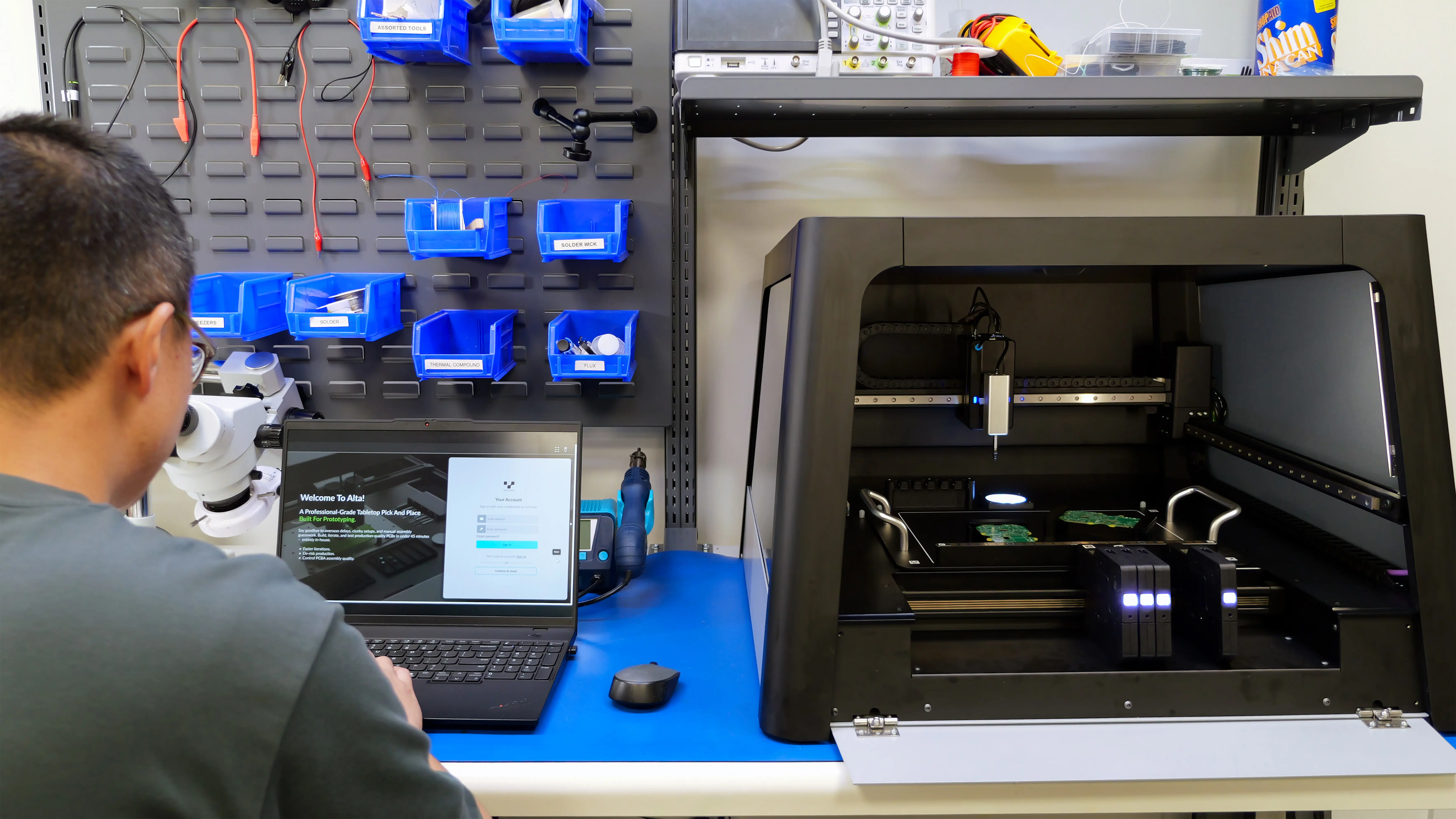
Pick and Place Files Explained: BOM, Centroid, Gerber, and CAD Data
- By: Ji-Won Park Yum
- Published: November 19, 2026 |
Modified: November 19, 2026 - Estimated read time: 6 minutes
- By: Ji-Won Park Yum
- Published: November 19, 2026 |
Modified: November 19, 2026 - Estimated read time: 6 minutes
A well-designed PCB does not guarantee a correct assembly. Inconsistencies between component lists, placement data, and machine configuration can introduce mistakes during PCB assembly.
Before placing a single component, a pick and place machine needs to know which components belong on the board, where they should be placed, and where to pick them up. This information typically comes from a combination of design files and component data, but how it gets translated into machine instructions varies between systems.
Understanding the file types and how they work together, can help engineers avoid setup errors and streamline PCB prototyping.
BOM: What components belong on the board?
A bill of materials (BOM) lists the components required to assemble a PCB. It typically includes reference designators (such as R1, C1, and U2), manufacturer part numbers, quantities, and values. Together, these details establish which components are needed and how they correspond to the design.
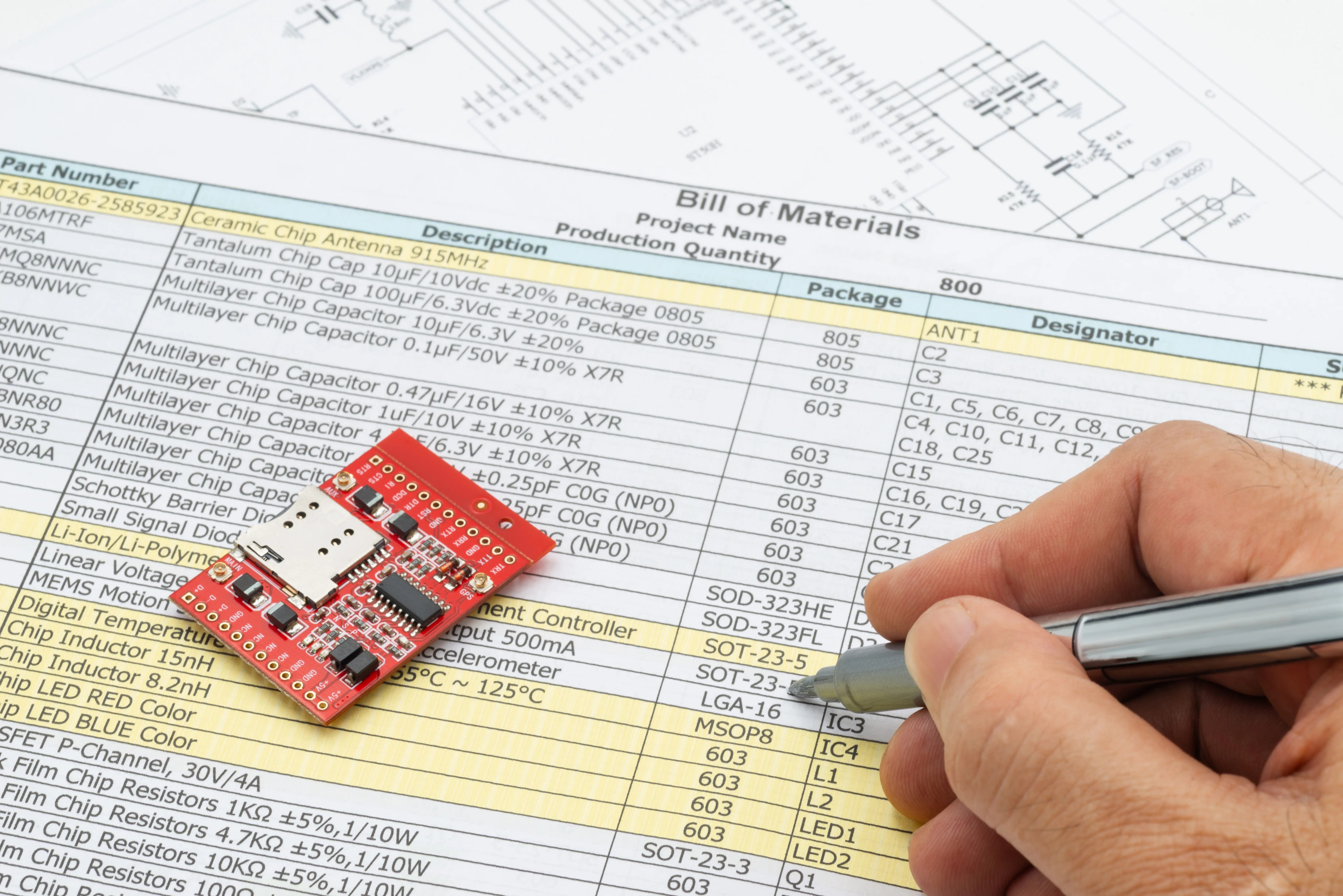
For example, a BOM might identify R1 as a 33 kΩ resistor with a manufacturer part number and package size. This ensures the correct component can be sourced and associated with R1, but it does not tell the assembly machine where that resistor should be placed. That is where placement data comes in.
Centroid file: Where do components go?
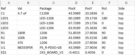
A centroid file, also known as a pick and place file, XY file, or component placement list (CPL), provides the position and orientation of each component on the PCB. It typically contains reference designators, X and Y coordinates, rotations, and the board side on which each component belongs.
Continuing with the previous example, while the BOM identifies what R1 is, the centroid file specifies where R1 should be placed and how it should be oriented.
Many pick and place systems use this information to generate placement instructions. Other systems require this information to be entered manually. However, a separate centroid file is not always necessary, as some assembly software can extract placement information directly from supported PCB design formats.
Gerber files: How is the PCB manufactured?
While BOMs and centroid files describe components and their placement, Gerber files primarily describe the PCB itself. They contain manufacturing data for individual board layers, including copper traces, solder mask, silkscreen, and solder paste openings.
These files are typically generated by exporting a PCB design from electronic CAD software (ECAD software) and are used by manufacturers to fabricate the bare board. Although the Gerber X3 standard can also include component information for assembly, conventional Gerber exports are primarily concerned with board manufacturing rather than defining a complete pick and place job.
eCAD files: Where does the information originate?
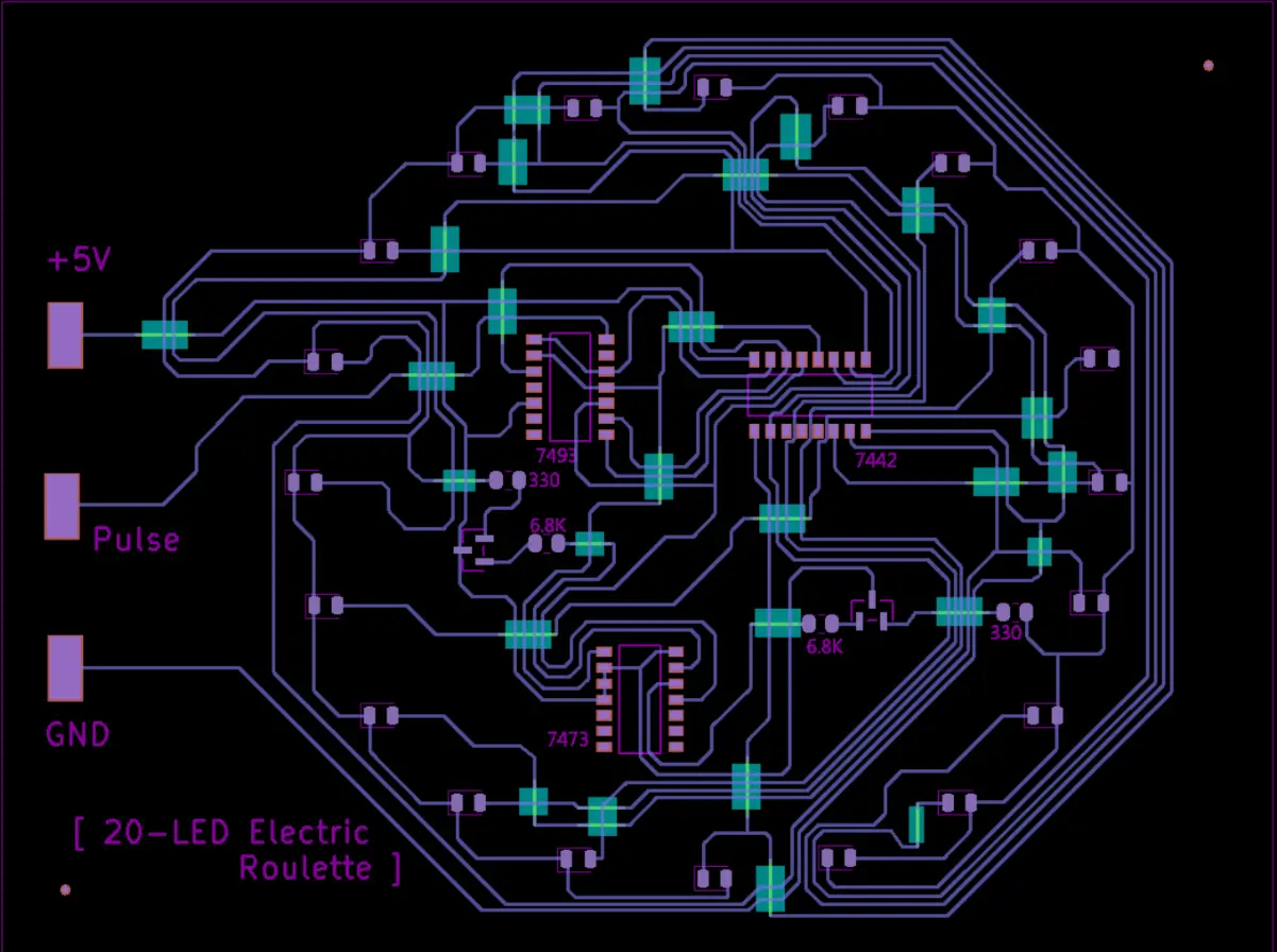
All this information originates from the electronic design process. Electronic CAD tools, such as KiCad and Altium Designer, allow engineers to design their PCBs while maintaining structured information about components, footprints, positions, rotations, and board geometry.
Unlike manufacturing exports, native eCAD files preserve the editable design information from which files such as Gerbers and centroid lists can be generated. Depending on the assembly system, engineers may need to export several separate files, or the software may be able to obtain the required information directly from a supported design format.
From PCB design files to pick and place machine setup
Having the correct design files is only part of preparing a pick and place machine for assembly.
The machine must also establish where the physical PCB is positioned, associate components with their corresponding feeders, and determine where each component can be picked up.
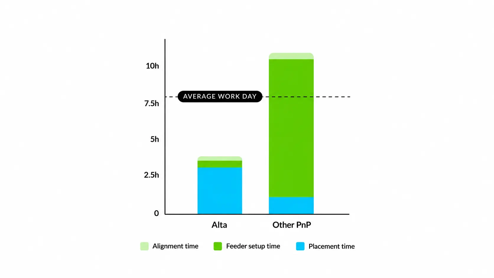
How much of this process happens automatically depends on the machine. Some desktop systems, such as the NeoDen YY1, involve manually configuring feeder positions and component information after importing placement data. Others, such as Opulo's LumenPnP, support automated feeder discovery with compatible hardware but still require certain setup and component assignment steps. Industrial platforms, including ASMPT SIPLACE, often incorporate intelligent feeders and automated calibration to streamline this process.
The distinction isn't simply whether a machine uses vision or automation, but how much work remains between importing a design and starting an assembly.
How Alta simplifies PCB assembly setup
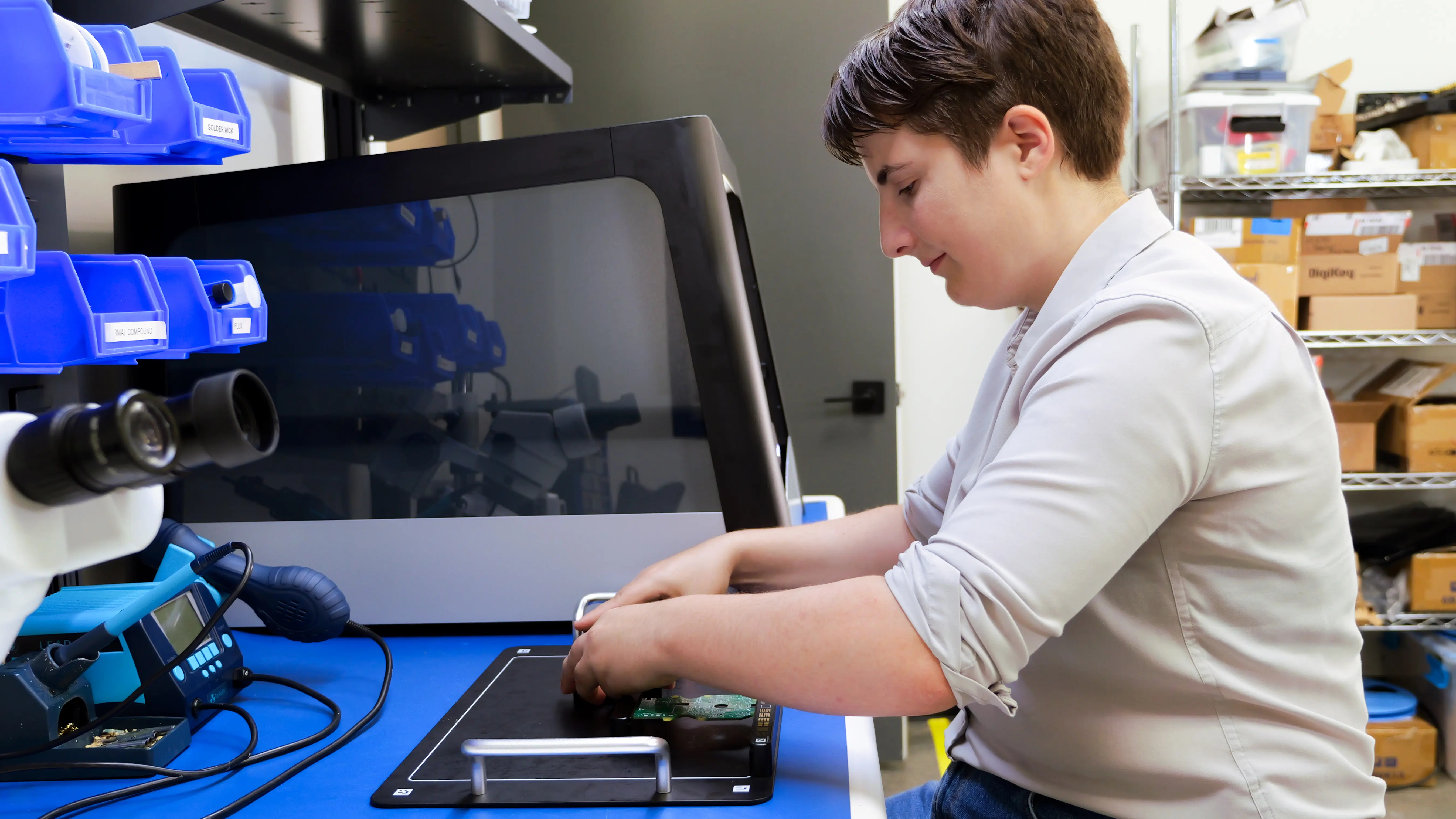
Alta is Voltera’s benchtop pick and place system with integrated solder paste dispensing. It is designed to bring a more streamlined setup experience to desktop PCB prototyping by reducing the manual configuration traditionally associated with preparing a pick and place job.
Rather than requiring users to manually configure component and feeder positions, Alta takes supported ECAD data and a BOM as inputs. Its vision system then identifies the physical locations of components and feeders, automating positioning setup and reducing the work required to translate a PCB design into machine instructions. This is especially valuable in prototyping environments, where engineers frequently revise designs, substitute components, or switch between projects. When every iteration introduces a new setup, reducing repetitive configuration helps engineers spend less time preparing equipment and more time building, testing, and refining their designs.
Interested in seeing how Alta simplifies PCB assembly? Book a feature brief with our team.
Check out our customer stories
Take a closer look at what our customers are doing in the industry.