White paper
Printing a Magnesium Zinc Battery with Saral Inks on PET
Printed batteries offer a thin and lightweight solution for powering electronics. This project is an example of printing a functional seven-layer battery, designed for use in moderately power-demanding electronics, such as security cameras, electric toothbrushes, portable lighting, handheld GPS devices, and toys.

- Saralon Saral printed battery suite
- Voltera NOVA
Video
Project Overview
Purpose
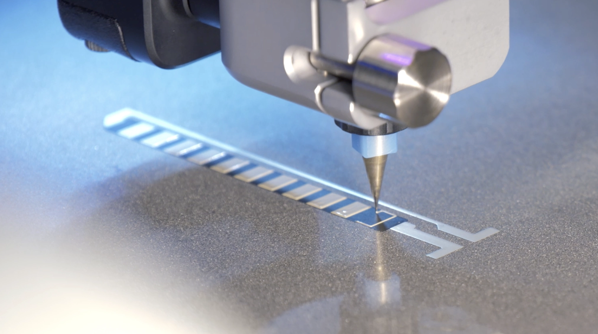
The purpose of this project is to demonstrate how we used Voltera NOVA to fabricate a functional multilayer printed battery on a flexible PET substrate, using a variety of conductive and insulating inks.
Design layout
Typically, a printed battery consists of five layers:
- Current collector layer for the anode
- Anode layer
- Separator layer with electrolyte
- Current collector layer for the cathode
- Cathode layer

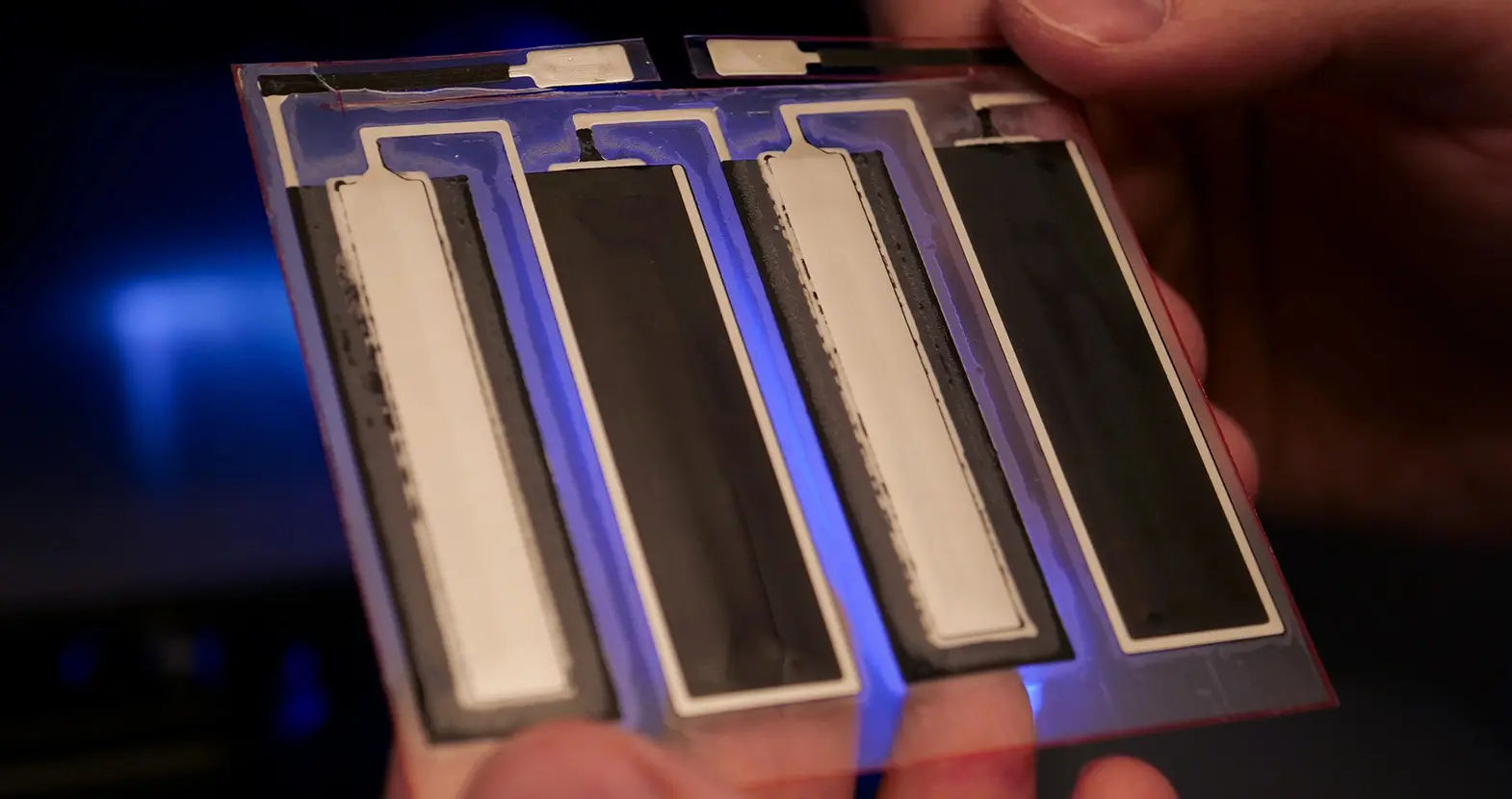
We segmented the battery into halves, each comprising four units, connected in series. As a result, our final print consisted of seven layers.

The printing sequence was as follows:
- Silver conductive layer
- Carbon current collector layer
- Zinc anode layer
- Manganese dioxide cathode layer
- Separator layer
- Hot melt glue layer
- Zinc chloride electrolyte layer
Desired outcome
Once the halves are laminated together, the cells align perfectly and do not exhibit any leakage. When connecting its two probes to the battery terminals, the multimeter shows a stable reading of about 2.4 V.
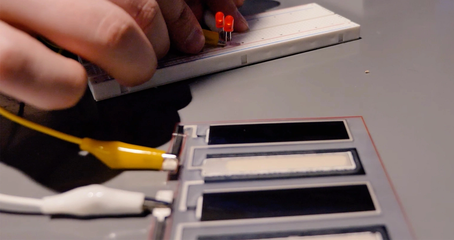
Functionality
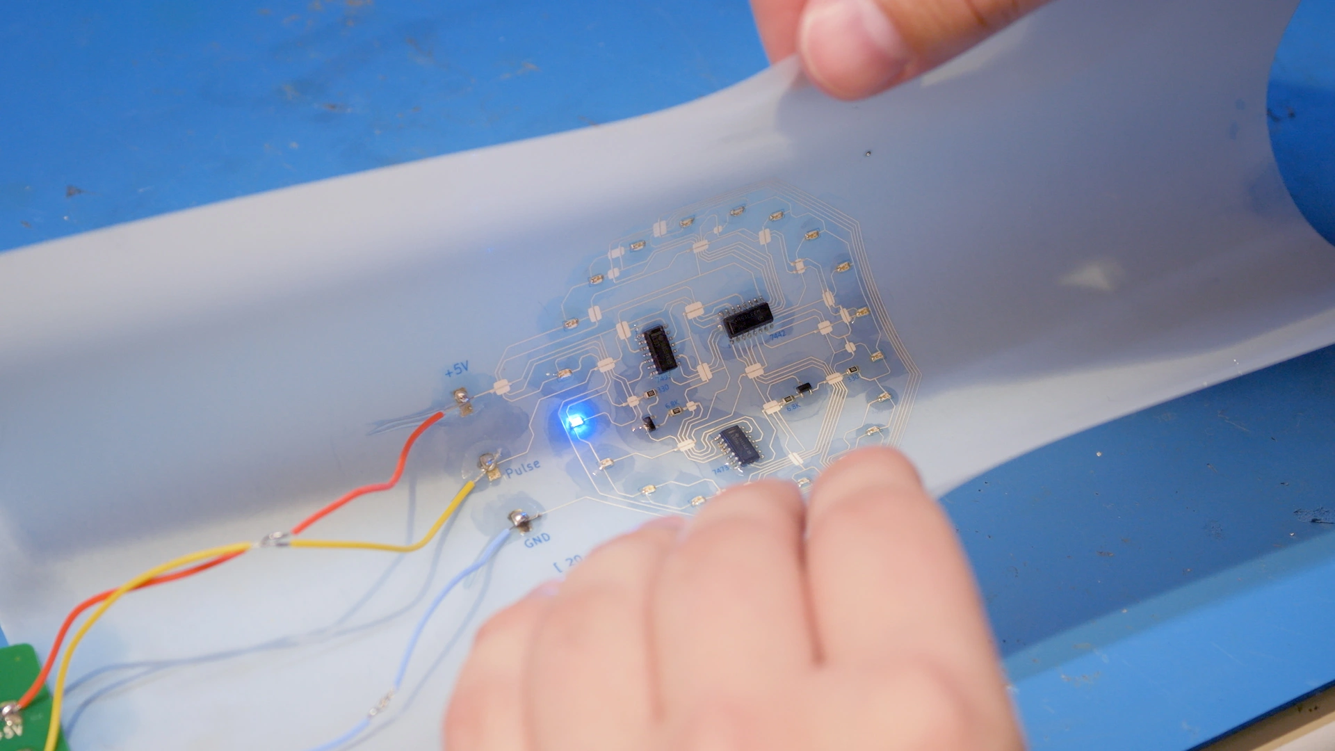
The device incorporating the Saral inks was able to operate at a voltage of 2.4 V, which can make the battery quite versatile. With a voltage of 2.4 V, a printed battery can power a range of devices from low-power electronics such as LEDs, to more demanding applications such as handheld GPS devices, depending on its capacity.
The dimensions for the battery are 90 mm L × 85 mm W × 0.75 mm H, with an initial capacity of about 1 mAh. Larger energy capacity and different voltages are achievable by varying the size and thickness of the layers, choosing different materials for electrochemical reactions, or adding more cells in series.
Printing the magnesium zinc battery
Silver conductive layer
This layer consists of a silver conductive circuit connecting the positive and negative terminals. The Saral Silver 600A Battery Ink used for this layer provides a moderate electrical conductivity (< 20 mΩ/sq at 25 μm), ensuring reliable current flow between the electrodes.
| Ink | Saral Silver 600A Battery Ink |
| Substrate | PET |
| Nozzle type | Nordson EFD 7018302 dispensing tip, 330 µm inner diameter |
| Probe pitch | 5 mm |
| Cure time and temperature | About 1 minute at 90°C |


Carbon current collector layer
This layer consists of carbon features that collect current from both the anode and cathode, covering all eight cells (the basic units that generate electrical energy through electrochemical reactions) across the halves. The Saral Carbon 700A Carbon Based Conductive Ink provides excellent adhesion on PET, with a moderate resistance of 30 Ω/sq at 25 μm, ensuring efficient collection of current.
| Ink | Saral Carbon 700 Carbon Based Conductive Ink |
| Substrate | PET |
| Nozzle type | Nordson EFD 7018302 dispensing tip, 330 µm inner diameter |
| Probe pitch | 5 mm |
| Cure time and temperature | About 1 minute at 90°C |


Zinc anode layer
This layer includes four cells that serve as the anode of the battery. The Saral Zinc 700 Battery Ink provides a sufficiently thick layer by one print, ensuring that the anode maintains a high conductivity and stability throughout its lifecycle. The high zinc content promotes efficient electron flow, which is critical for maintaining the battery's overall energy output and longevity.
| Ink | Saral Zinc 700 Battery Ink |
| Substrate | PET |
| Nozzle type | Nordson EFD 7018302 dispensing tip, 330 µm inner diameter |
| Probe pitch | 5 mm |
| Cure time and temperature | About 1 minute at 90°C |


Manganese dioxide cathode layer
This layer includes four units that serve as the cathode of the battery. Similar to the The Saral Zinc 700 Battery Ink, the Saral MnO2 800 Battery Ink provides a sufficiently thick layer by one print, ensuring that the cathode maintains a high conductivity and stability throughout its lifecycle.
| Ink | Saral MnO2 800 Battery Ink |
| Substrate | PET |
| Nozzle type | Nordson EFD 7018302 dispensing tip, 330 µm inner diameter |
| Probe pitch | 5 mm |
| Cure time and temperature | About 1 minute at 90°C |


Separator layer
This layer consists of eight units printed with a water-based ink to create separation between the anode and the cathode layers. Once dried, it becomes porous to allow ion travel.
| Ink | Saral BatBarrier 600 Battery Ink |
| Substrate | PET |
| Nozzle type | Nordson EFD 7018107 dispensing tip, 840 µm inner diameter |
| Probe pitch | 5 mm |
| Cure time and temperature | About 1 minute at 90°C |


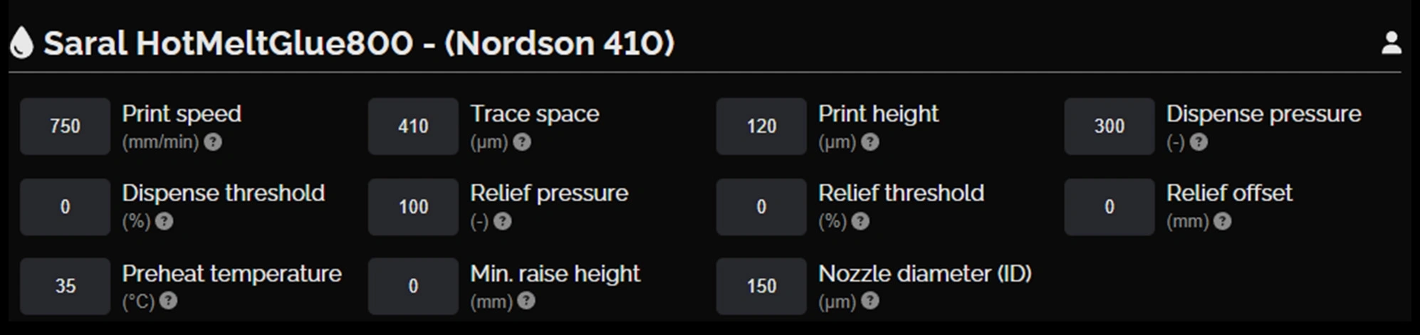
Hot melt glue layer
Excluding the terminals, anodes, and cathodes, this layer covers the whole surface of the final print and facilitates lamination.
| Ink | Saral HotMeltGlue 800 Battery Ink |
| Substrate | PET |
| Nozzle type | Nordson EFD 7018260 dispensing tip, 410 µm inner diameter |
| Probe pitch | 7 mm |
| Cure time and temperature | About 5 minutes at room temperature |


Zinc chloride electrolyte layer
This layer consists of eight units of electrolytes, each slightly smaller than the anode/cathode units. They provide electrolytes that facilitate the movement of ions between the anode and cathode.
| Ink | Saral BatElectrolyte 700 Battery Ink |
| Substrate | PET |
| Nozzle type | Nordson EFD 7018333 dispensing tip, 250 µm inner diameter |
| Probe pitch | 5 mm |
| Cure time and temperature | About 10 minutes at room temperature to allow absorption into the separator layer |


Laminating the halves of the printed battery together
Once the last layer was printed and dried, we cut out part of the PET substrate to leave the terminals exposed. We then folded the print from the middle, carefully aligning the fiducial marks.
Next, we inserted the PET into the laminator at 120°C, with the terminals going in last. This was to prevent leakage of the electrolyte to neighboring units and causing short circuits in the battery. When subjected to heat, the hot melt glue layer becomes sticky and holds the halves together.

Challenges and advice for printing batteries on flexible substrates
Nozzle compatibility
Nozzle clogging was an issue while working on the separator layer, which was printed with an ink that tends to dry quickly and is prone to forming agglomerates if left unused for an extended period.
In addition, due to the thin, water-like consistency of the water-based BatBarrier 600 Battery Ink, we had to refine print settings to adjust for over-dispensing in order to achieve the intended thin, uniform traces.
We mixed the ink using a dual asymmetric centrifugal mixer before printing. This process, which lasted for 10 minutes at a speed of 2,000–2,500 rpm, proved effective in breaking up the agglomerates and alleviating clogging. Additionally, removing excess water from the ink (we removed 1.8 mL) helped resolve issues with over-dispensing.
Layer leakage
Because the electrolyte layer was printed with a water-based zinc chloride ink, it posed some challenges during lamination. To avoid leakage, we noted that sufficient time was required for the electrolyte layer to absorb into the separator layer before laminating the halves together.
As the design varies, the volume of inks dispensed is different. It is therefore difficult to pinpoint an exact time required for the electrolyte layer to absorb. Some visual signs that indicate full absorption include:
- A noticeable lowering of the level of the electrolyte layer
- Drying and uniformity of the print surface
- A change in the color of the electrolyte layer to a dull white hue
It is also important to note that achieving a higher short circuit current usually involves increasing the thickness and size of the electrolyte layer. Consequently, more time should be allowed for the layer to dry and settle properly.
Conclusion
The thickness of the final print (excluding the PET substrate) is 500 µm, which highlights the potential of printed batteries to be ultra thin and flexible. More importantly, this flexibility renders printed batteries highly customizable — they can store energy in various shapes and sizes to suit product design, instead of the other way around.
In this project, we experimented with zinc and magnesium dioxide inks as the anode and cathode, but a wide variety of materials can be used for printed batteries, including lithium cobalt oxide, carbon nanotubes, and vanadium oxide, to name a few. If you're interested in learning more about flexible printed batteries, check out the following resources:
Frequently asked questions
What is a flexible printed battery and how does it work?
A flexible printed battery is an energy storage device made by printing functional layers such as current collectors, electrodes, separators, and electrolytes onto a flexible substrate like PET. Electrical energy is generated through electrochemical reactions between the anode and cathode, while ions move through the electrolyte and separator.
How are flexible printed batteries different from traditional batteries?
Unlike conventional batteries that use rigid metal cans or pouch cells, flexible printed batteries are planar, ultra-thin, and mechanically flexible. They typically offer lower capacity, but excel in form-factor customization, low-profile integration, and compatibility with flexible or wearable electronics. Printed batteries are especially well suited for low-power devices where space, weight, and shape are critical design constraints.
What materials are used in flexible printed batteries?
Flexible printed batteries use a combination of functional inks, including conductive inks such as silver or carbon, active electrode materials like zinc and manganese dioxide, separator layers, electrolytes, and encapsulation or barrier materials. The choice of materials determines the battery’s voltage, capacity, flexibility, and stability, and can be tailored to specific applications.
Printing multilayer flexible, stretchable, and conformable electronics?
NOVA’s Plan feature makes it easy.