Cut Tape vs. Reels for Pick and Place Machines
Cut Tape vs. Reels for Pick and Place Machines
- By: Shuxuan Jiang
- Published: July 7, 2026 |
Modified: July 7, 2026 - Estimated read time: 6 minutes
- By: Shuxuan Jiang
- Published: July 7, 2026 |
Modified: July 7, 2026 - Estimated read time: 6 minutes
For new product introduction (NPI) teams, the choice between SMT reels and cut tape is more than a packaging decision. It affects inventory planning, feeder setup, and how quickly a team can move from “parts arrived” to “first board placed.” In PCBA prototyping, where bill of materials (BOMs) change frequently, that difference can have a real impact on iteration speed.pi
What are SMT cut tape and reels?
In surface mount technology (SMT) assembly, common component packaging formats include reels, cut tape, tubes/sticks, trays, and loose components. Among these, reels and cut tape (or simply “tape”) are especially common for components used with pick and place machines, because both rely on carrier tape that can be indexed by a feeder.

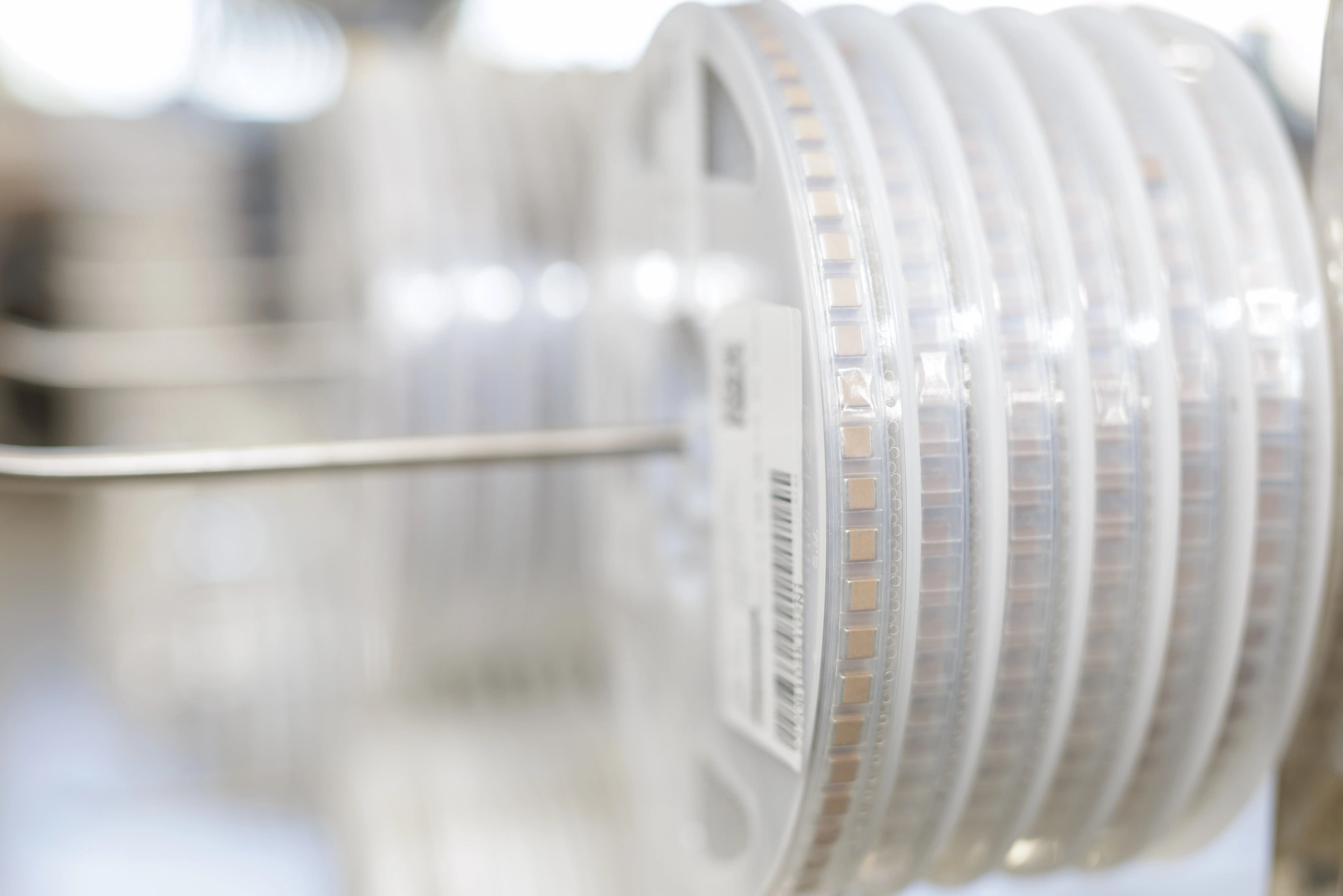
An SMT reel is the full tape supply wound on a hub. A reel typically includes a leader section before the first component and a trailer section after the last component, giving the feeder enough empty tape to grip, advance, and peel the cover tape before placement begins.
7" (180 mm) reels are standard for smaller quantities and are common for prototyping and short runs. They typically contain 1,000-3,000 parts depending on component size, while 13" (330 mm) reels typically contain 3,000-10,000 parts and are shipped by distributors by default for volume orders.
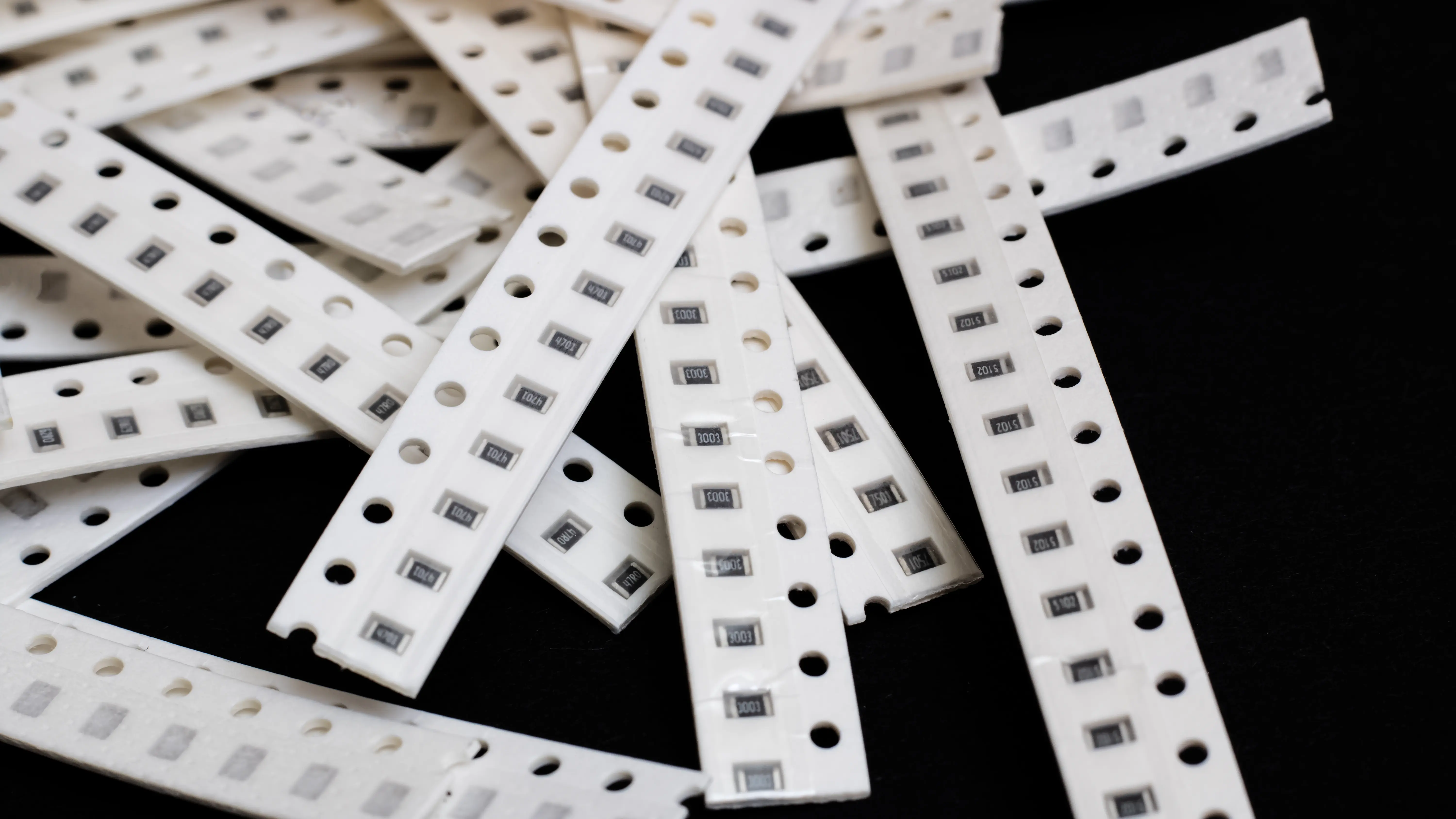
Cut tape is a segment of an SMT reel intended for low-quantity use. The component pockets, sprocket holes, and cover tape are fundamentally the same, but the strip is not spooled and may not include enough leader or trailer tape for standard automated feeding. Cut tape can be short or long, depending on the quantity ordered, but it is typically supplied as a raw strip rather than a feeder-ready reel.
Cut tape vs. reel: Inventory commitment
The economics are straightforward. Teams rarely need thousands of the same resistor, capacitor, or integrated circuit (IC) for an early prototype run. Most prototype BOM quantities are in the tens to low hundreds, which maps better to a strip of tape than to a full reel. Cut tape helps teams avoid excess inventory, especially when the BOM is still changing.
Reels make more sense when a component is used repeatedly across builds. If a team uses the same 0603 resistor, 0402 capacitor, LED, connector, or IC across multiple boards, keeping that part on a reel can reduce repeated handling and setup effort. In other words, cut tape protects BOM flexibility, while reels protect repeatability.
Cut tape vs. reel: Setup efficiency
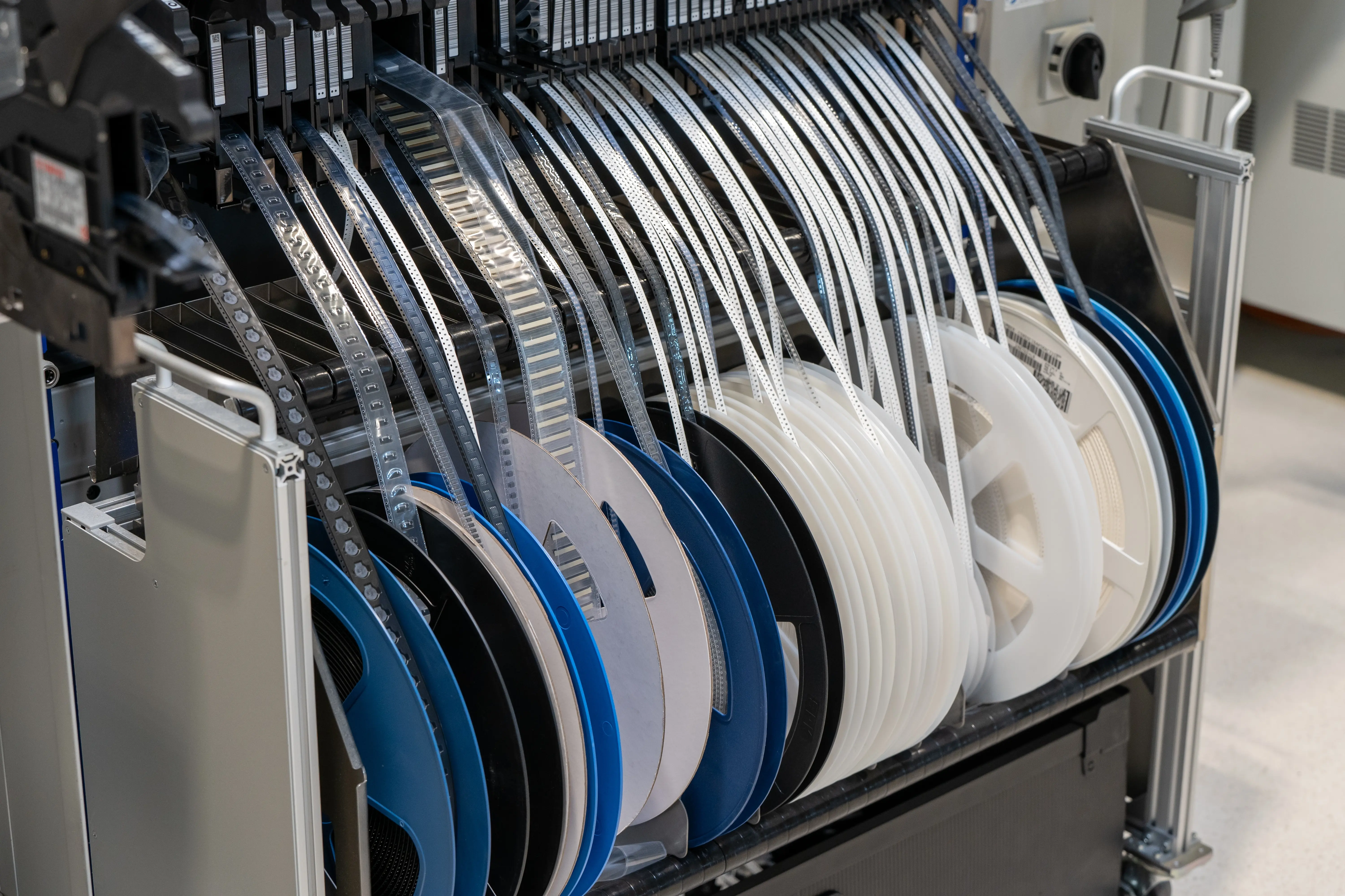
Although the difference between cut tape and reels is simple on paper, it becomes more important during setup. On many traditional pick and place machines, loading a reel can still require several manual steps: verifying tape width and pitch, threading the tape through rollers and guides, ensuring the cover tape peels cleanly, assigning the correct feeder or lane, selecting the nozzle, teaching the pick location, and setting part orientation.
Incorrect setup can create downstream problems. The wrong tape width can jam the feeder. The wrong carrier pitch or feed rate can misposition the component. A feeder, lane, or library mismatch can cause the machine to pull from the wrong component source.
Cut tape has a different setup challenge. Because it is supplied as a strip rather than a spooled reel with leader and trailer sections, it is not always suitable for standard tape feeders. Depending on the machine, cut tape may need to be placed in a cut tape strip feeder, mounted in a holder that keeps the tape flat and properly aligned, spliced to leader tape, or prepared manually before placement. In many strip feeder workflows, the cover tape is peeled off entirely and the exposed strip is held in place for the machine to pick from.
This makes cut tape attractive for low-quantity prototype BOMs, but it can add handling friction. Short strips can be harder to secure, exposed components can be easier to disturb, and unlabeled strips can get mixed up in storage. These issues are manageable, but they can become a bottleneck when a prototype build uses dozens of unique line items.
| Cut tape | Reels | |
|---|---|---|
| Inventory commitment | Lower | Higher |
| Feeding method | May require a strip feeder, tape holder, splicing, or manual preparation | Continuous automated feeding through tape feeders |
| Setup during frequent part swaps | Easier for short prototype runs. No need to mount and tune a full reel every time the BOM changes. | More involved if the BOM is still changing. Each reel change can add setup time. |
| Repeatability across the same build | Good when the strip is held flat, labeled clearly, and used in a controlled workflow | Strong once the reel is loaded and the feeder setup is validated |
| Handling risk | Higher if strips are exposed, short, unlabeled, or manually handled between builds | Lower once loaded, but still requires proper feeding, cover tape handling, feeder setup, and storage |
Recommendations for PCBA prototypes
Because PCBA prototypes are often one-off or short-lived, buying full reels for dozens of uncertain line items can strand inventory and slow down revision cycles rather than speeding iteration up. That said, reels make more sense for recurring passives and stable active footprints, especially as a project moves from engineering validation test (EVT) into design validation test (DVT), production validation test (PVT), or low-volume bridge builds.
For prototyping teams, the best approach is usually a hybrid policy:
- Keep rare, expensive, alternate, or unstable BOM items on cut tape until usage becomes predictable.
- Put recurring passives and proven house parts on reels early because they amortize setup effort.
In practical terms, teams should store not just the component, but the validated setup state: feeder lane, feed pitch, pickup height, nozzle, vision orientation, and library entry. The more of this setup state that lives inside the machine workflow, rather than in disconnected notes or operator memory, the easier it becomes to repeat a known-good build after a BOM change.
That is where purpose-built PCBA prototyping machines with intuitive software can create real leverage. With guided setup, reusable job data, and solder paste dispensing built into the same workflow as placement, systems like Voltera Alta help reduce the amount of process knowledge engineers must reconstruct every time a component is reused.
Building a PCBA prototyping workflow? Follow Alta's development and be the first to know when it's available.
Conclusion
As PCB assembly moves earlier in the product development cycle, the real question is not which format to order; it's whether your workflow can handle both without rebuilding setup from scratch each time.
For prototyping teams, that means the next generation of pick and place workflows needs to support both flexibility and repeatability: flexible enough for changing EVT and DVT builds, but repeatable enough to preserve setup state as the design matures. The less time engineers spend reconfiguring the machine, the more time they can spend validating the product.
Want to learn more about choosing the right PCBA prototyping machine? Check out the following blogs:
Check out our customer stories
Take a closer look at what our customers are doing in the industry.