White paper
Connecting Flexible and Stretchable Substrates to Printed Circuit Boards
Connecting flexible circuits to traditional printed circuit boards (PCBs) is commonly called flexible-to-rigid interconnections. They enable flexible sensors, displays, wearables, and other flexible electronics to communicate with microcontrollers, power management systems, and external devices.


- ACI SS1109 stretchable silver ink
- ACI FC3203 flexible carbon ink
- Voltera NOVA
- V-One PCB printer
- NOVA materials dispensing system
- Würth Elektronik 687140149022 FFC connector
- TE Connectivity AMP Connectors 487923-1 contact crimp pin connector
- Amphenol ICC (FCI) 66226-004LF 4 position FFC connector header
- CW Industries CWR-142-10-0203 IDC connector
- 3M electrically conductive adhesive transfer tape 9703
- TLKKUE B0B1B33TZJ 10 mm snap connectors
- Guangshunle B0CXLL458K 15 mm snap connectors
- Arduino Micro controller
Project overview
Purpose
The goal of this project was to validate five different ways of making reliable, accessible interconnections between flexible and rigid circuits — a common use case for a lot of our customers and essential to making flexible prototypes compatible with standard test equipment, breadboards, or rigid control systems.
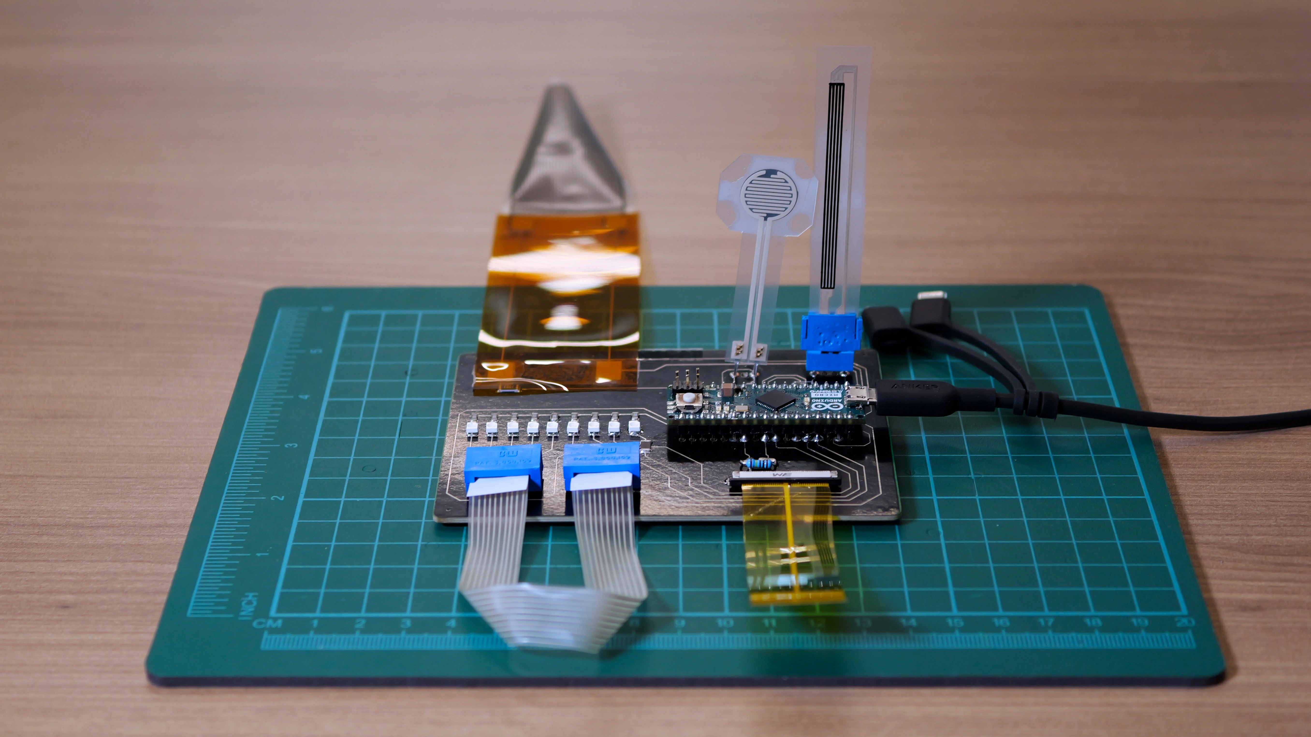
Design
The project consisted of three parts:
- Printing the flexible circuits
- Capacitive touch sensor
- Force sensitive resistor (FSR)
- Flex sensor
- Strain gauge
- Ribbon cables
- Printing the rigid circuit
- Connecting flexible circuits to the rigid PCB using six types of commercially available connectors
- Zero insertion force (ZIF) connector
- Crimp connector
- Flexible flat cable (FFC) connector
- Snap connector
- Insulation displacement contact (IDC) connector
- Z-axis conductive tape
| Connector | Connected to | Type |
|---|---|---|
| Würth Elektronik 687140149022 FFC connector |
| ZIF |
| Amphenol ICC (FCI) 66226-004LF 4 position FFC connector header |
| FFC |
| TE Connectivity AMP Connectors 487923-1 contact crimp pin connector |
| Crimp |
| TLKKUE B0B1B33TZJ 10 mm snap connectors | ECG electrodes | Snap |
| Guangshunle B0CXLL458K 15 mm snap connectors | Heated mitten | Snap |
| CW Industries CWR-142-10-0203 IDC connector |
| IDC |
| 3M electrically conductive adhesive transfer tape 9703 |
| Z-axis conductive tape |
Desired outcome
Once the interconnections have been established, they should exhibit both mechanical fit and electrical integrity. To achieve that, each connector should fit snugly with no slippage or misalignment under normal handling and usage. In addition, the contact resistance should be low, effectively near-zero.
Although we didn’t set metrics for measurements for the printed sensors, as a general rule, they should respond accurately to their respective physical inputs (pressure, strain, bending, capacitive touch) and maintain reliable electrical connections through repeated flexing or stretching.
Functionality
While all the methods we showcased are feasible for making interconnections, each of them offers different durability, reusability, and suits different applications.
| Method | Flexibility | Reusability | Notes |
|---|---|---|---|
| ZIF | Moderate | Moderate to high | Contact resistance ~25 mΩ-40 mΩ, durable up to 10k-20k insertion cycles |
| Crimp | Low | High | Reliable, rigid connection; ideal for bench setups |
| FFC | Moderate | Moderate | Used for flat, flexible cables; requires compatible locking connector |
| Snap | Moderate | Moderate to high | Good for removable modules; common in wearables |
| IDC | Low | High | Quick connections for ribbon/stretch cables |
| Z-axis tape | High | Low to moderate | Flexible; adhesive may degrade with repeated use. Many are single use only. |
The rigid PCB successfully helped us test the result of our interconnections, with total series resistance across each interconnection well below 1Ω, providing negligible signal loss. This aligns with common connector specifications and makes the connectors suitable for sensor interfacing.
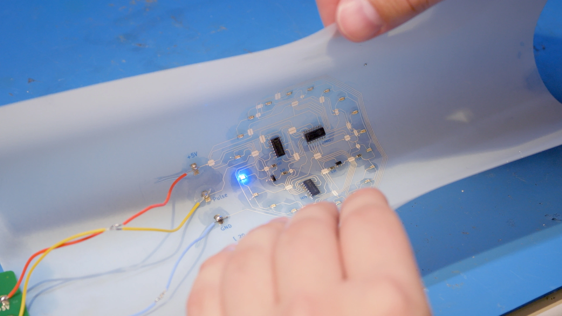
Printing the flexible circuits
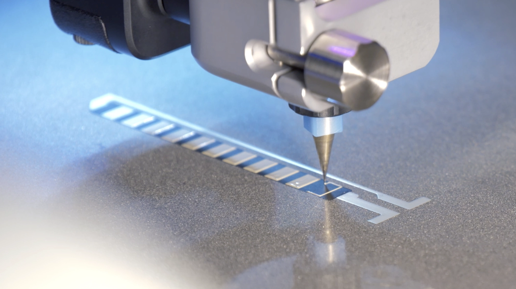
The flexible sensors were printed using the NOVA materials dispensing system with varying print settings.
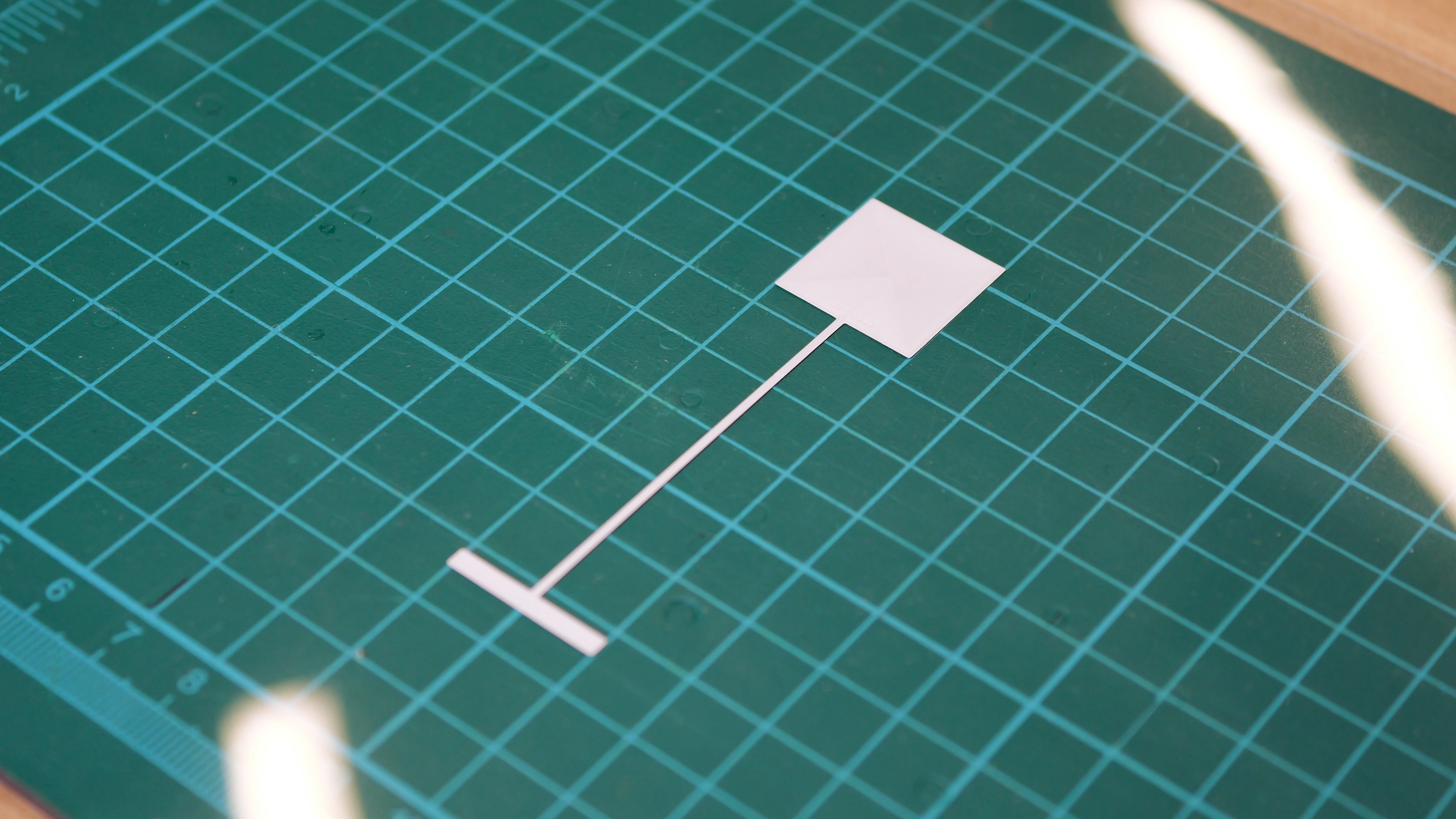
Printing the capacitive touch sensor
This circuit consists of a touch electrode (large square pad at the top), and a trace leading down (and the small contact region at the bottom). Once printed and cured, the circuit was covered with Kapton tape to insulate and stabilize the touch interface. When a finger or conductive object approaches the pad, it increases the capacitance of that electrode relative to ground.

| Ink | ACI FS0142 flexible silver ink |
| Substrate | PET |
| Print time | 6 minutes 6 seconds |
| Cure time and temperature | 150°C for 15 minutes |
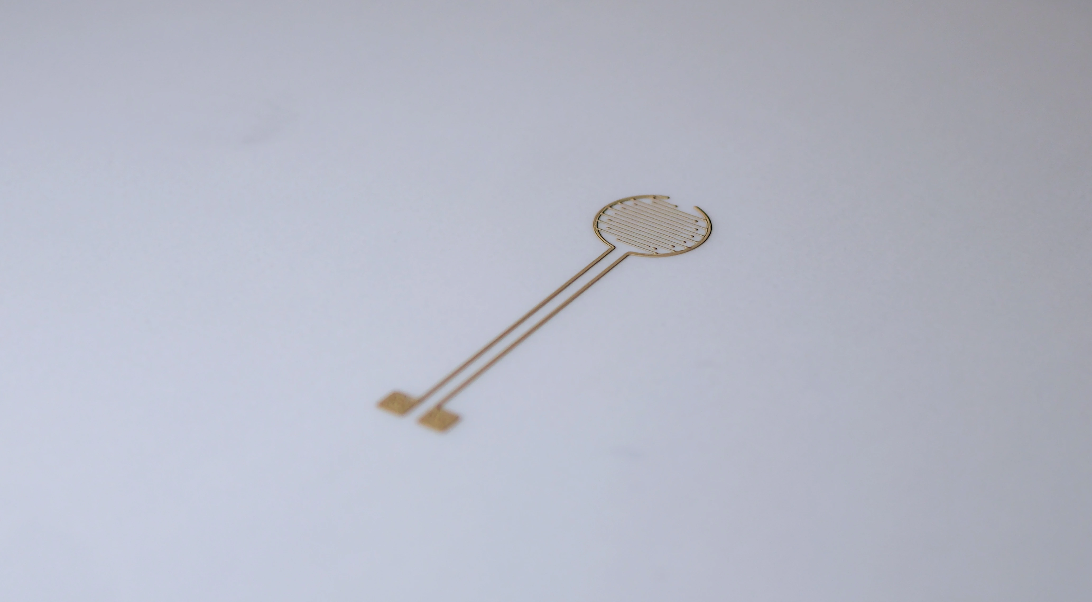
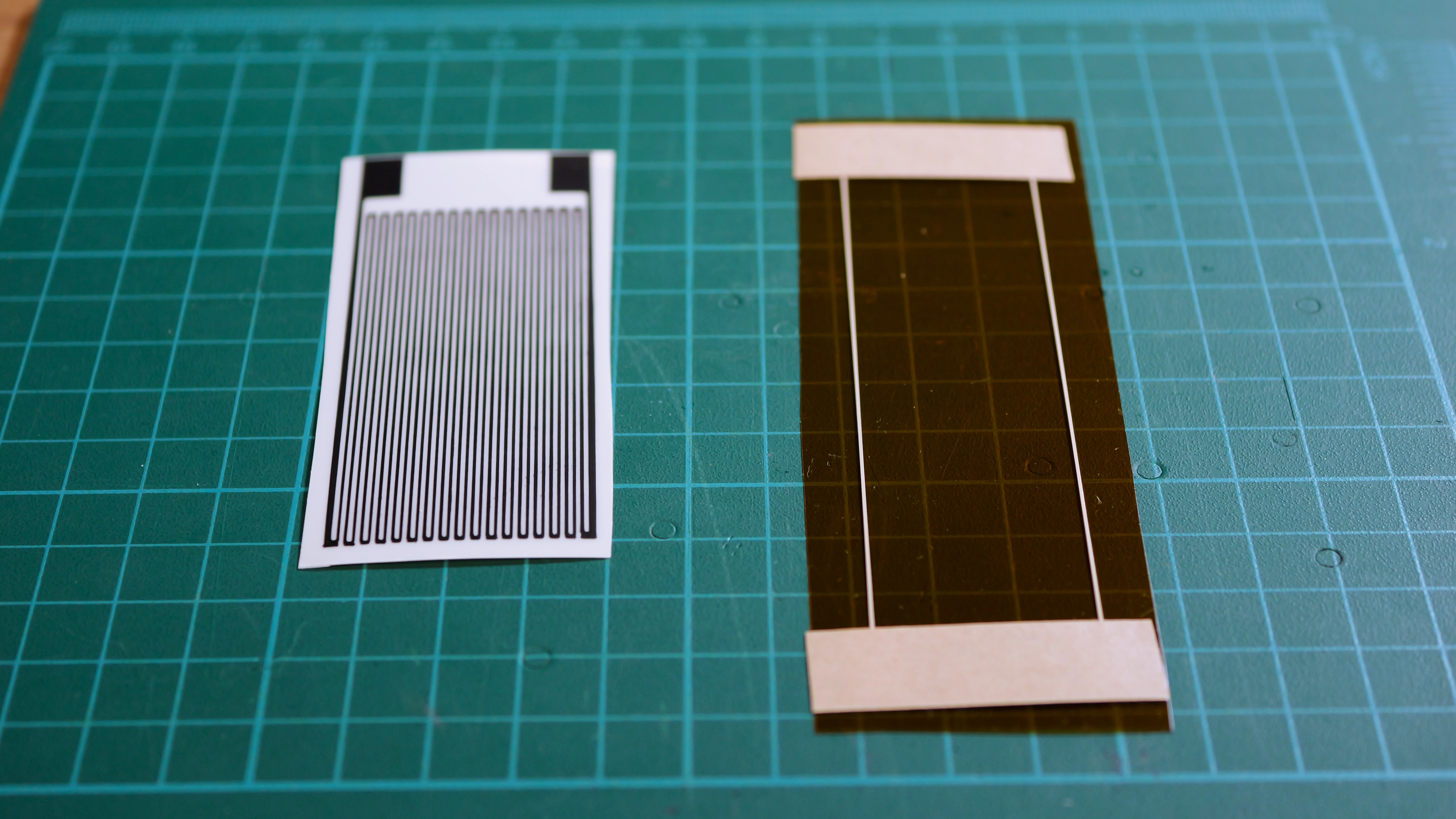
Printing the force sensitive resistor (FSR)
This circuit consists of a piezoresistive element (red) as well as fine mottled traces (blue) that serve as interdigitated electrodes. When pressure is applied, the carbon film compresses and resistance drops between the interdigitated silver electrodes.

| Ink |
|
| Substrate | PET |
| Print time |
|
| Cure time and temperature |
|
Printing the flex sensor
This circuit consists of traces that form an electrically resistive sensing element (blue) as well as traces that form conductive interconnects (red). When the sensor bends, the carbon trace deforms, increasing its resistance. This resistance change is measured via the silver interconnect and used to quantify the degree of flex or curvature.
| Ink |
|
| Substrate | PET |
| Print time |
|
| Cure time and temperature |
|
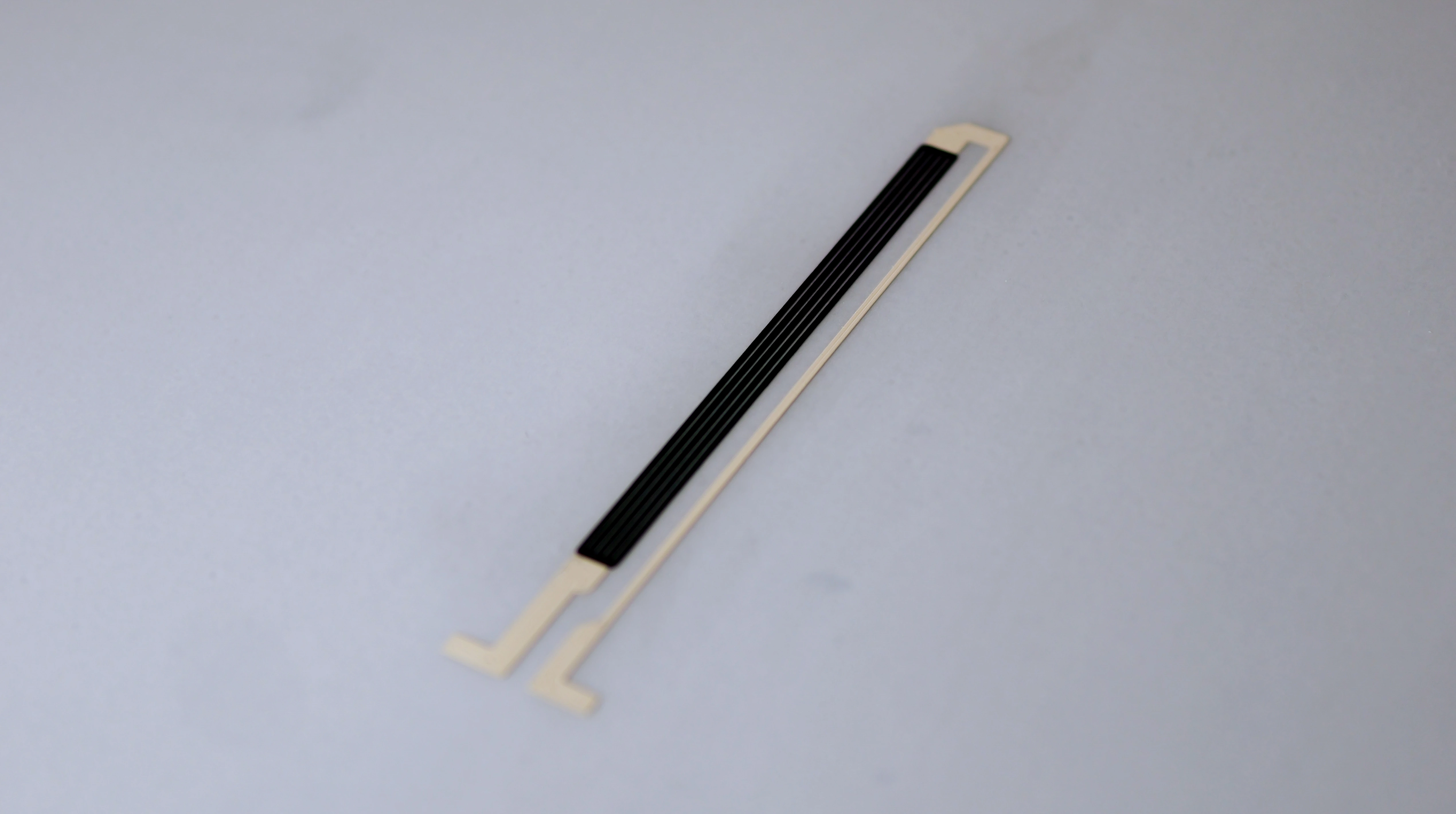
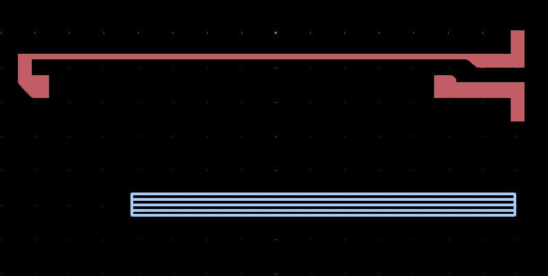
Printing the strain gauge and the ribbon cable
The strain gauge and its interconnect were printed as two separate circuits:
- A serpentine resistive strain gauge (in red)
- A thin custom ribbon cable (in blue) acting as its signal extension
The gauge’s silver pads were aligned with the ribbon cable’s contact pads and bonded using 3M anisotropic Z-axis conductive tape to ensure a solderless electrical connection.

| Ink |
|
| Substrate |
|
| Print time |
|
| Cure time and temperature |
|
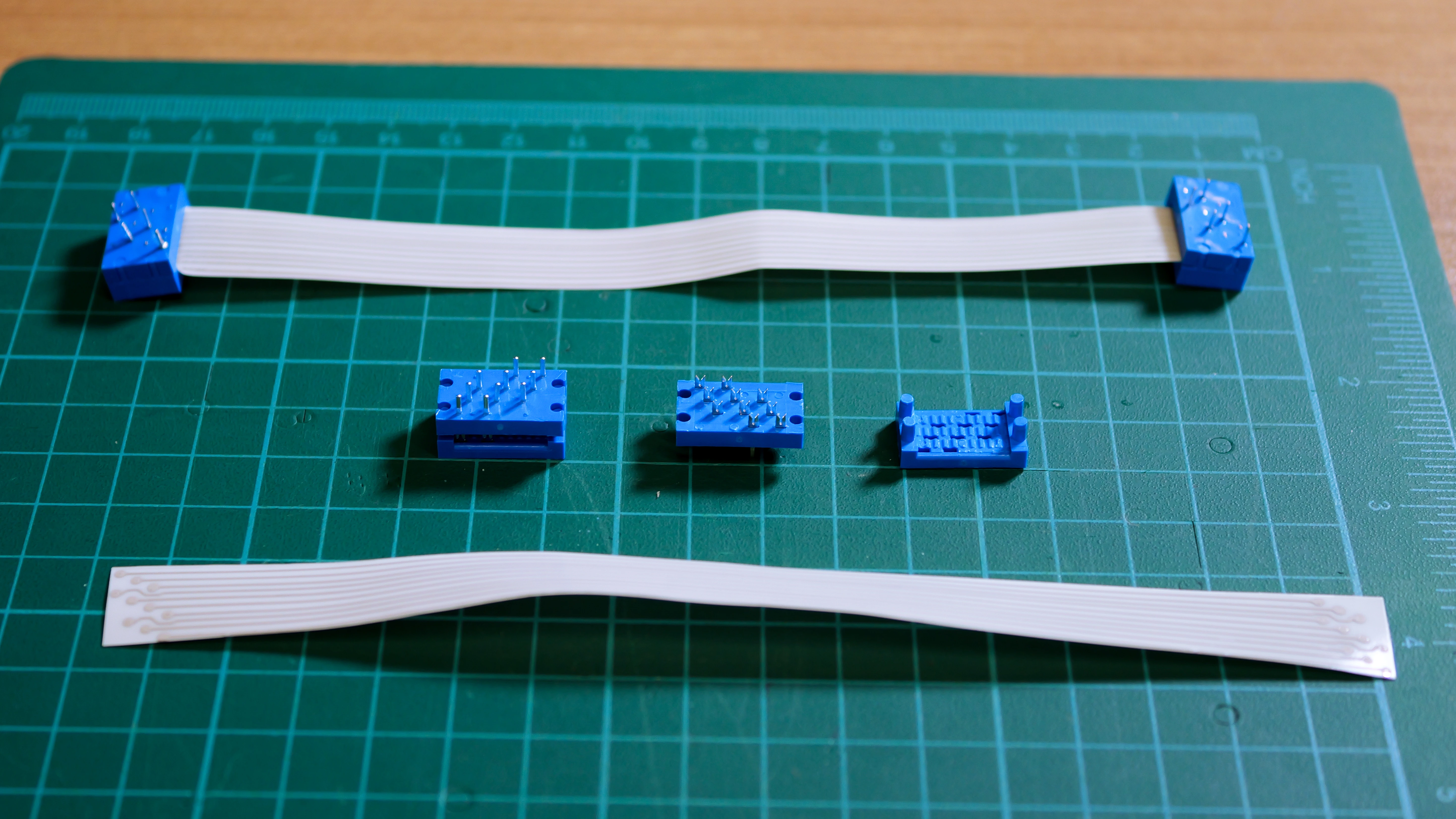
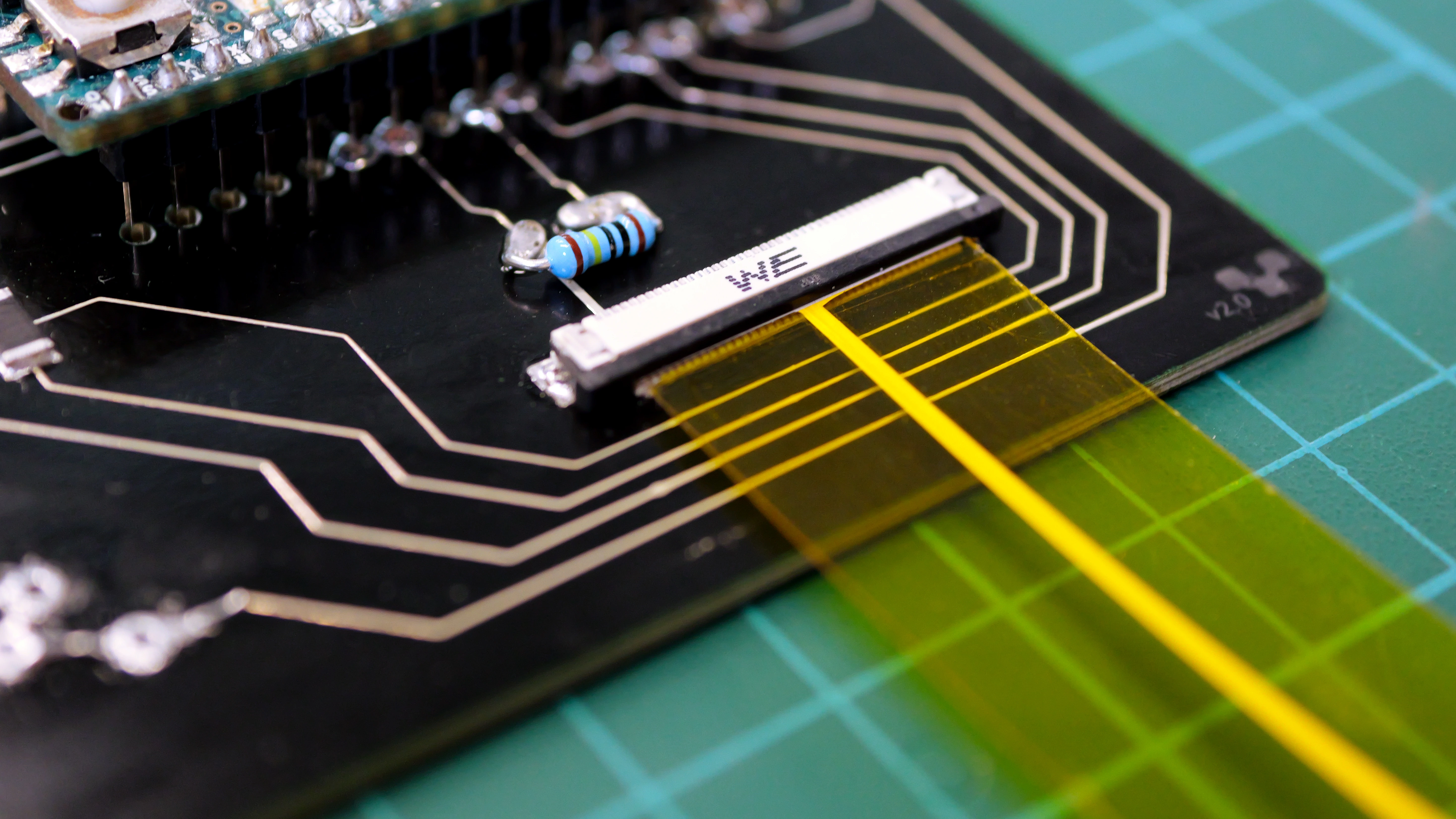
Printing the ribbon cable
The ribbon cable is a custom multi-conductor flat cable with parallel conducting traces evenly spaced, each one acting as an individual wire in the cable. The circular pads at each end are for electrical connection to the rigid circuit board with the IDC connectors.

| Ink | ACI SS1109 stretchable silver ink |
| Substrate | TPU |
| Print time | ~13 minutes 28 seconds |
| Cure time and temperature | 135°C for 5 minutes |
ECG sensors and heated mitten
These flexible circuits were printed in previous applications and showcase the use case for snap connectors, which are ideal for wearable and textile-based electronics. Snap connectors are small, lightweight, and durable, making them perfect for applications that require repeated attachment and detachment, such as medical sensors and smart garments. They also provide a secure mechanical bond while maintaining user comfort and are easy to integrate into fabric or soft substrates.
Check out the following white papers for details:
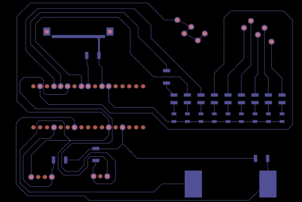
Printing the rigid circuit
This circuit was designed for integrating and testing flexible sensors and connectors. We first drilled through holes for the connectors. We then printed the circuit using the V-One PCB printer.
The board routes signals from multiple connectors to a central microcontroller (Arduino Micro). Each sensor’s signal path includes passive components (e.g. resistors, capacitors), then branches to I/O pins and visual feedback via LEDs.
| Ink | NovaCentrix HPS-U11 silver nanoparticle ink |
| Substrate | FR1 |
| Nozzle type | Voltera plastic nozzle |
| Probe pitch | 5 mm |
| Print time | 9 minutes 30 seconds |
| Cure Time and Temperature | 150°C for 30 minutes |
After curing the ink, we inserted copper rivets into the holes to provide robust physical anchoring. We then dispensed solder paste, placed the components onto the board, and ran a reflow cycle.
Connecting flexible circuits to the PCB
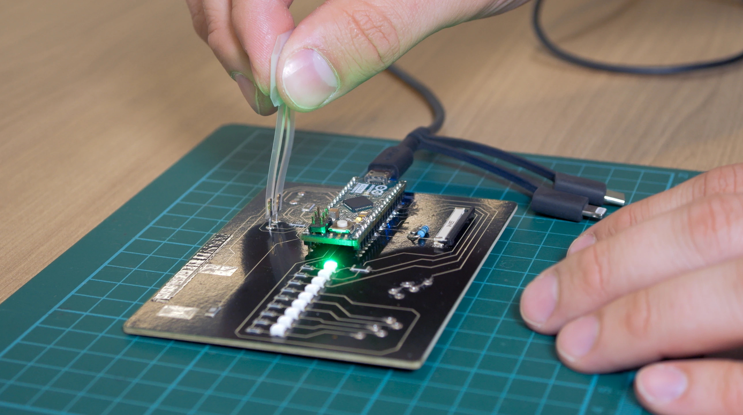
Connecting the capacitive touch sensor
This sensor was connected to the rigid PCB using a ZIF connector. We inserted the tail of the PET face-down (for bottom-contact) into the ZIF connector on the rigid PCB. We then closed the latch of the ZIF connector, clamping the tail in place. The advantages of this method includes:
- Low-profile, great for slim interfaces
- Non-permanent, easy replacement during prototyping
- No soldering required
- Stable contact for repeated use
Connecting the force sensitive resistor
The connection to the rigid PCB is made using a crimp connector. The TE Connectivity AMP crimp pins were mechanically forced through the PET substrate at the silver contact pads. The crimping arms of each pin were then folded over and flattened tightly against the substrate to create a secure connection.
This offers several advantages:
- Robust electrical connection
- Low-profile
- Reusable, ideal for prototyping and testing
Connecting the flex sensor
The flexible tail with silver pads was inserted into an Amphenol "clincher" FFC connector located on a rigid PCB. This connector clamps onto the pads, creating a secure, solder-free contact that relies on mechanical pressure to maintain electrical connectivity. That makes it non-destructive and reusable, ideal for testing and prototyping flexible sensors.
Connecting the strain gauge
The Z-axis adhesive electrically connects the sensor pads of the strain gauge to the extension circuit and subsequently to the rigid board through vertical conduction only, preventing lateral shorts while also providing a low-profile, solderless bond.
This makes it especially advantageous for heat-sensitive substrates like TPU or PET, where soldering could cause damage. The adhesive also eliminates the need for bulky connectors or reflow processes, ideal for fast assembly and prototyping.
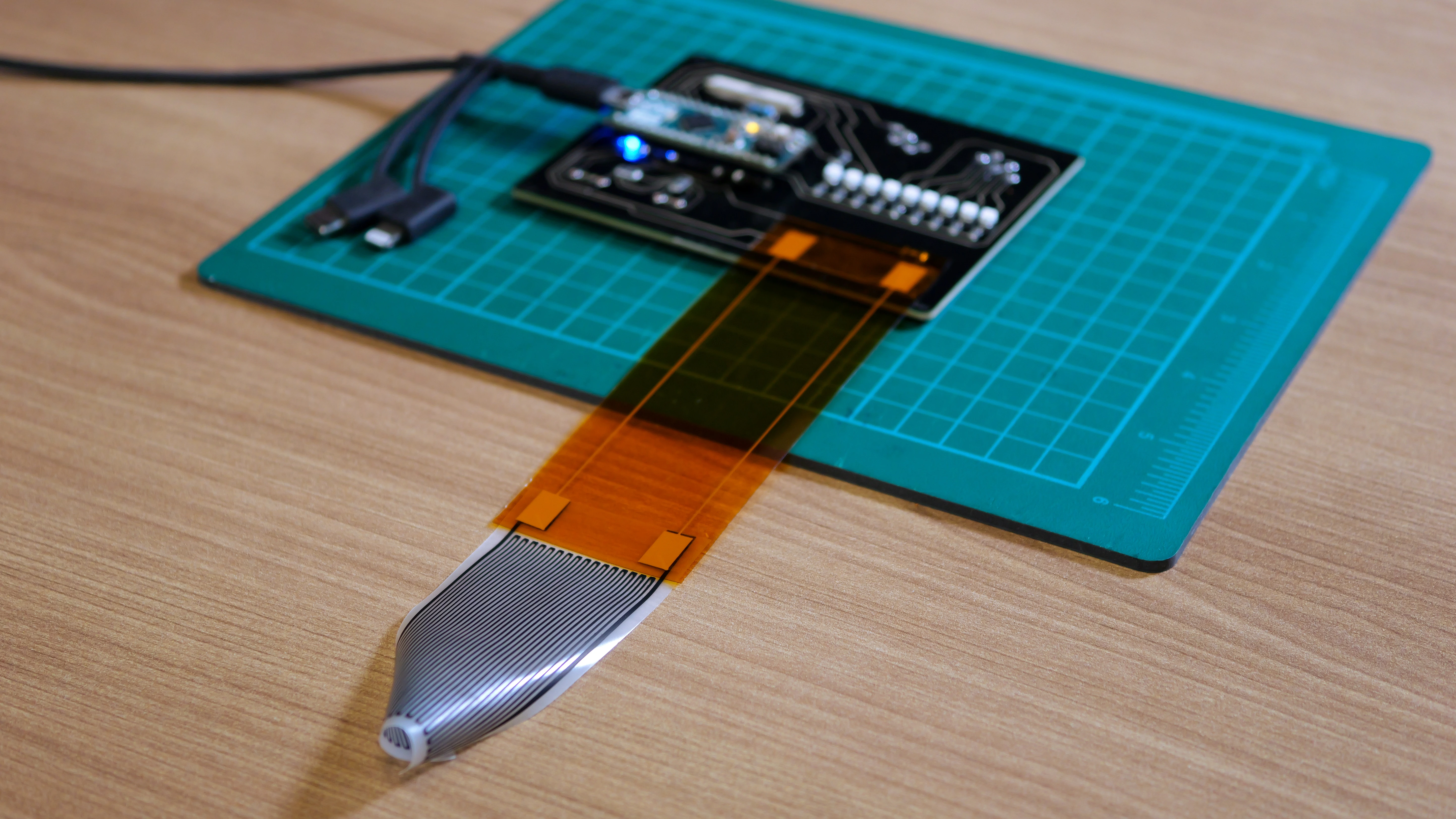
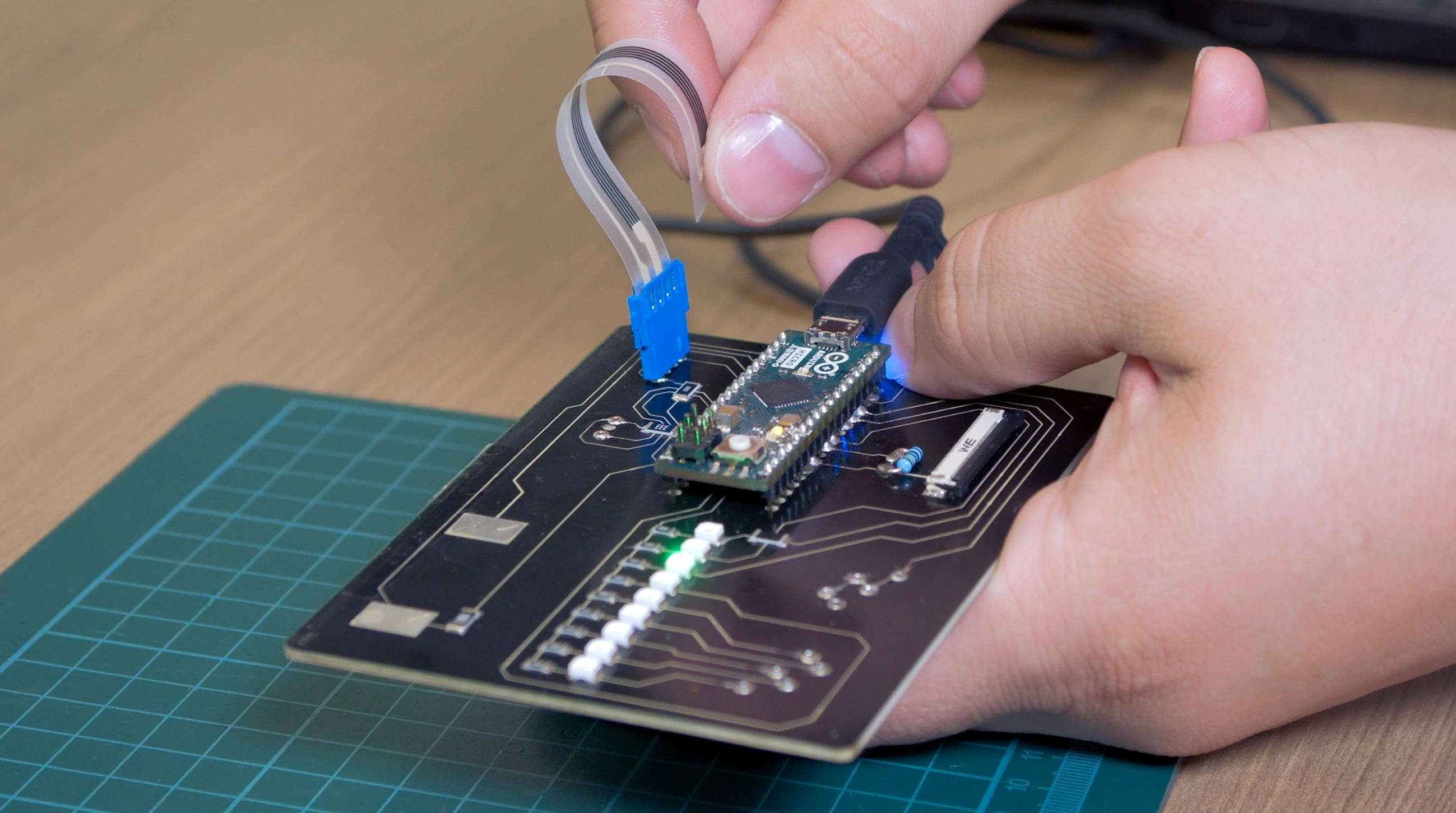
Connecting the ribbon cable
The connector pierces the substrate and makes contact with the conductive traces, allowing secure mechanical and electrical attachment.
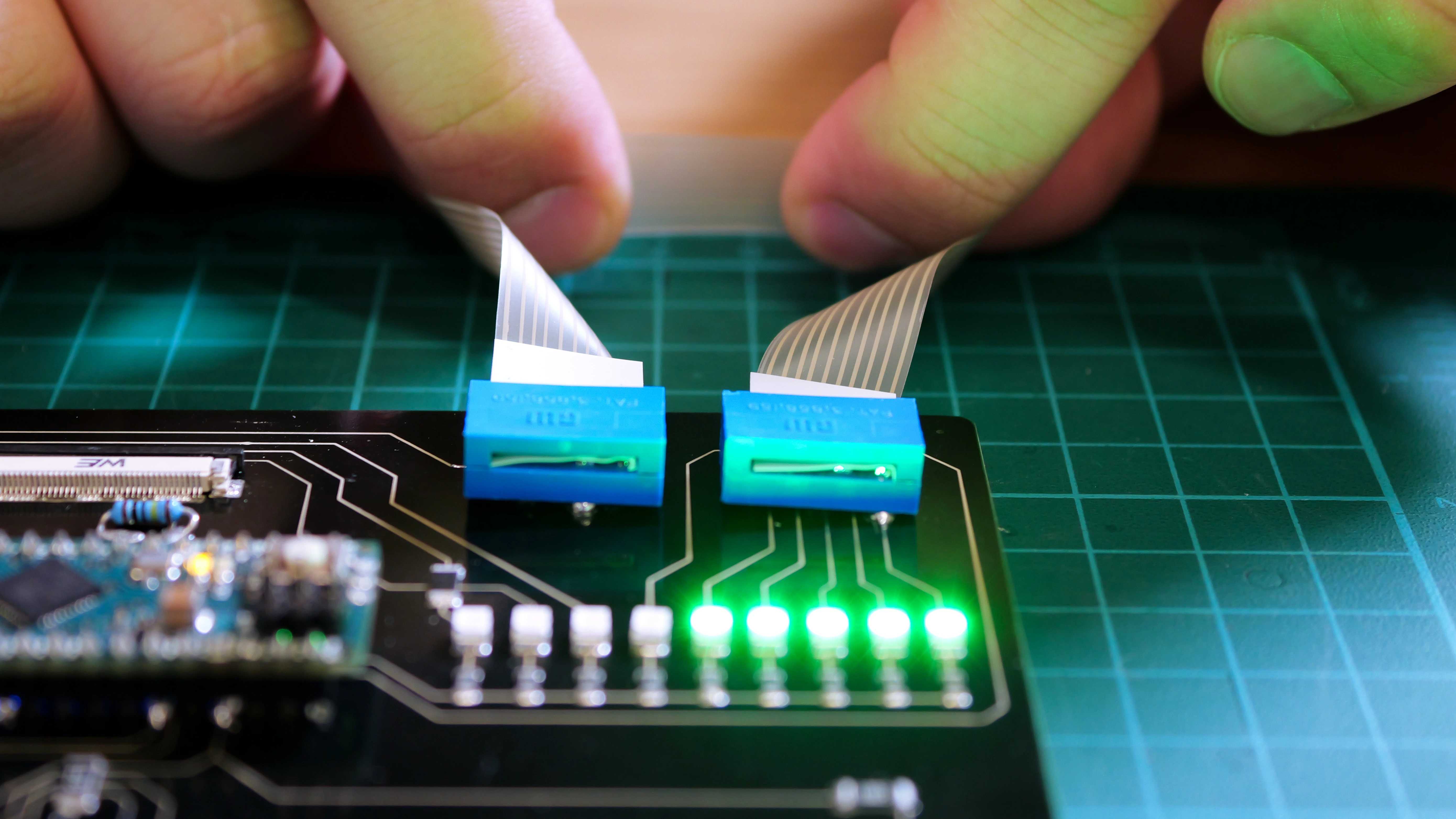
This offers several advantages:
- Seamless integration with no soldering or assembly needed
- Ultra-thin and lightweight compared to bundled wires.
- Customized length and pitch
- Handles movement and flex without mechanical strain on individual conductors
Challenges and advice
Reliability of Z-axis conductive tape
Initial experiments with Z-axis conductive tape for component mounting revealed unreliable connections, especially under conditions of strain or flex. This tape is best suited for static or semi-flex applications, and applying sufficient vertical pressure is crucial to maintain good electrical contact. For more robust and permanent connections, especially in industrial applications, thermoset anisotropic conductive films are commonly used.
Material selection and curing conditions
During our initial testing, printing sensors with silver ink on PET frequently resulted in cracking. Adjustments included optimizing print thickness, selecting alternative inks (ACI SS1109, SC1502), and introducing dielectric layers as buffers to improve durability and resistance range.
Conclusion
By optimizing material choices, print parameters, and connector integration, we demonstrated reliable pathways for sensor signals. The five practical techniques — ZIF, crimp, snap, IDC, and Z-axis tape — each offer unique advantages for wearables, medical devices, and flexible prototypes. These solutions empower designers to overcome integration hurdles while maintaining signal integrity across dynamic interfaces.
If you’re interested in our other projects involving the interface of flexible and rigid circuits, take a look at:
- Printing a Flexible Membrane Keyboard with Conductive Silver Ink and Dielectric Ink on PET
- Printing Strain Gauges on TPU laminated on a Glove for Remote Hand Control
- Printing a Flexible PCB with Silver Ink on PET
Working with printed electronics and need help making interconnections? Book a meeting to speak with one of our technical representatives.
Frequently asked questions
What is a flex-to-board connector?
A flex-to-board connector is a mechanical and electrical interface that links a flexible circuit (PET/TPU-based sensor, ribbon cable, etc.) to a rigid PCB. It provides a low-resistance, solder-free, and often reusable connection while protecting delicate flexible traces from mechanical stress. Common examples include ZIF, FFC, crimp, snap, IDC connectors, and Z-axis conductive tapes.
What are common flex PCB connector types?
There are several categories of connectors used to interface flexible circuits with rigid PCBs, each suited for different materials, mechanical requirements, and prototyping workflows.
- ZIF connectors: Clamp flexible tails; ideal for repeated use.
- FFC/clincher connectors: Grip exposed pads; good for ribbon cables.
- Crimp connectors: Strong, low-resistance mechanical connections.
- Snap connectors: Used in wearables; easy to attach/detach.
- IDC connectors: Fast, reliable parallel connections for ribbon cables.
- Z-axis conductive tapes: Ultra-thin, solderless bonding for heat-sensitive substrates.
Printing multilayer flexible, stretchable, and conformable electronics?
NOVA’s Plan feature makes it easy.