White paper
Printing a Decimal Counter Circuit with Silver Conductive Ink on FR1
A decimal counter is a digital circuit that cycles through zero to nine using logic components. It is essential in clocks and timers. Making a decimal counter using seven-segment displays offers great opportunities for students to learn sequential logic, clock signals, and circuit integration.

- Voltera Conductor 3 silver ink
- Voltera T4 solder paste
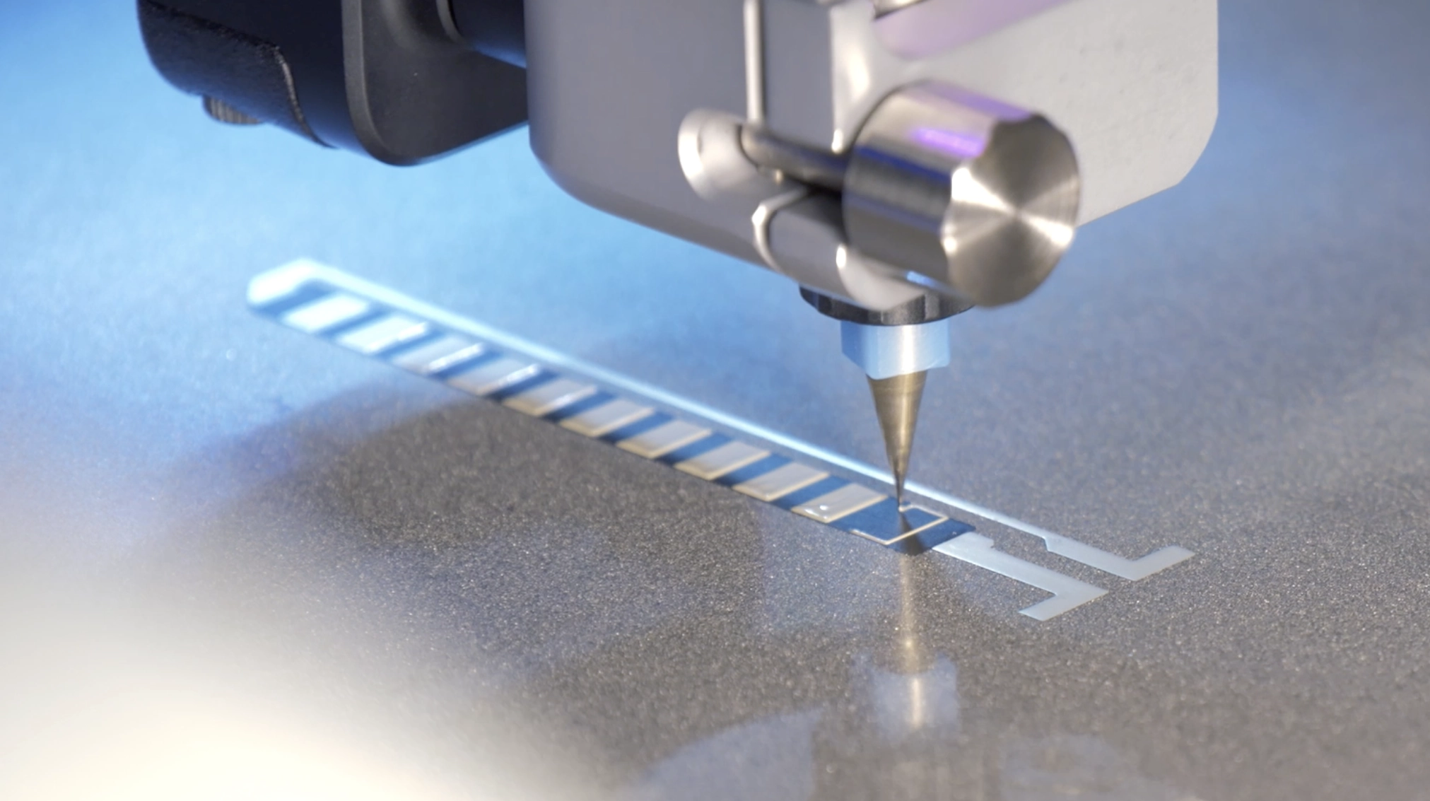
- Voltera V-One PCB printer
- Voltera disposable nozzles
- Linear voltage regulator
- Switching voltage regulator
- NE555DR timer
- Variable resistor
- Seven-segment displays
Project overview
Purpose
The goal of this project was to demonstrate PCB development through key concepts:
- Linear and switching regulators
- Variable resistors
- Seven-segment displays
- Prototyping techniques
- Conductive trace printing
- Component placement
- Solder reflow
Design
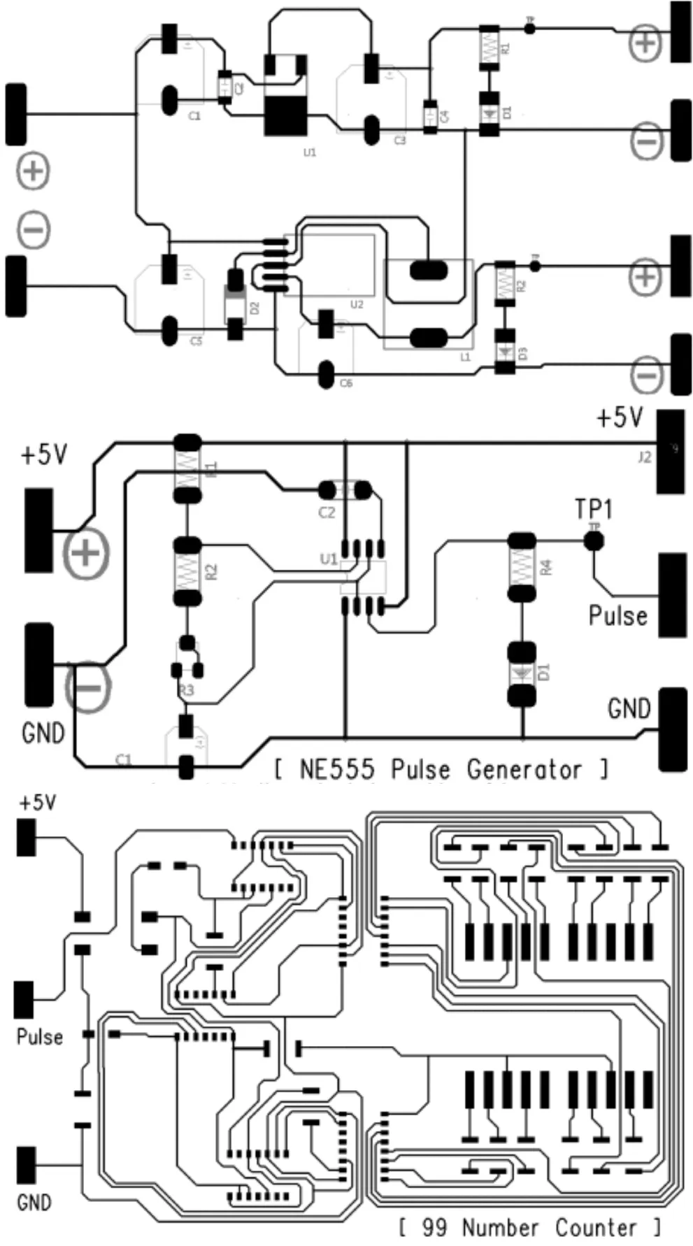
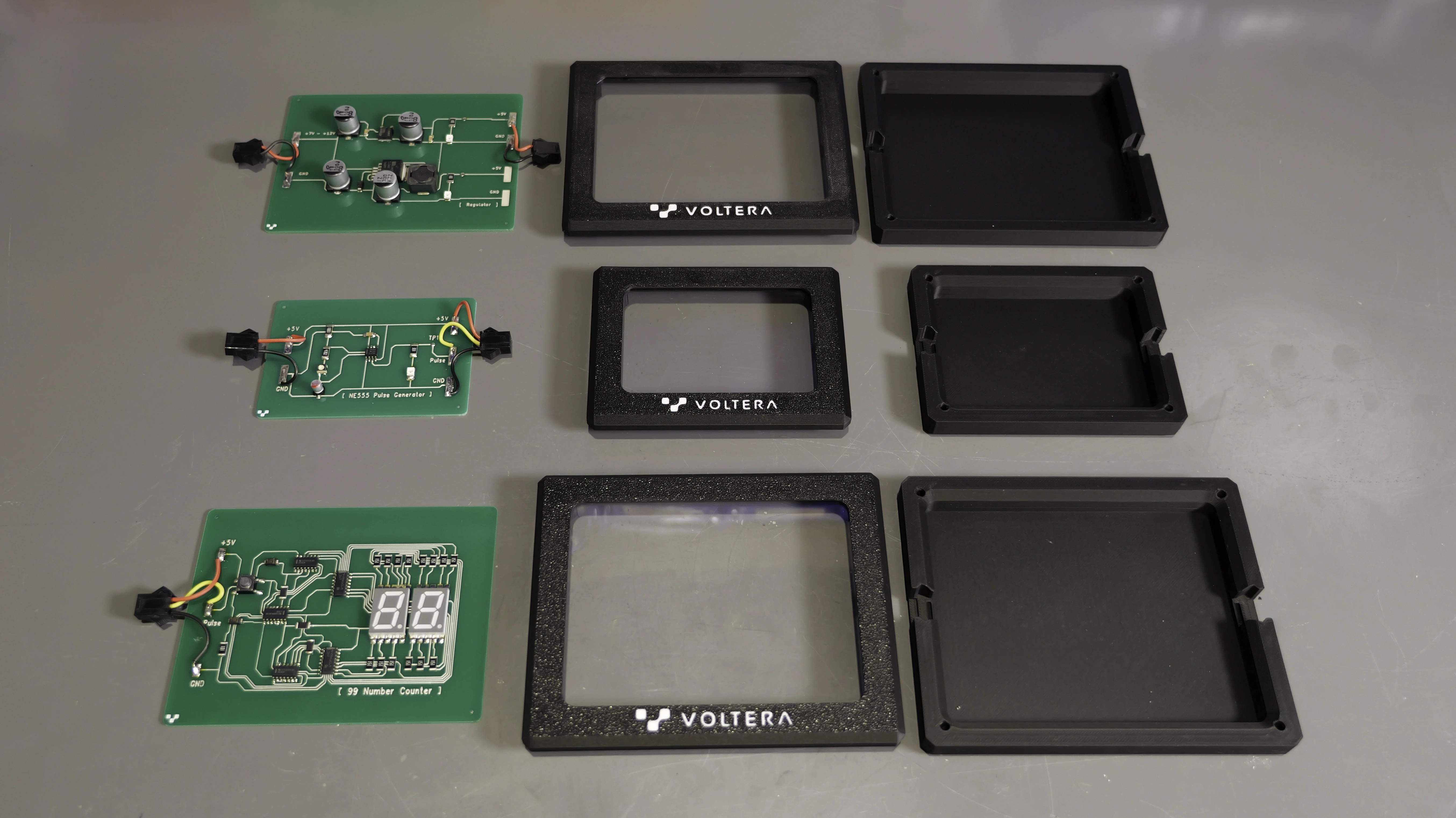
The original PCB layouts were provided by ITIZ, Voltera’s authorized reseller in Korea. We modified the design to create an integrated circuit system, which was comprised of three interconnected PCBs:
- Voltage regulator board
- Pulse generator board
- Decimal counter board
Desired outcome
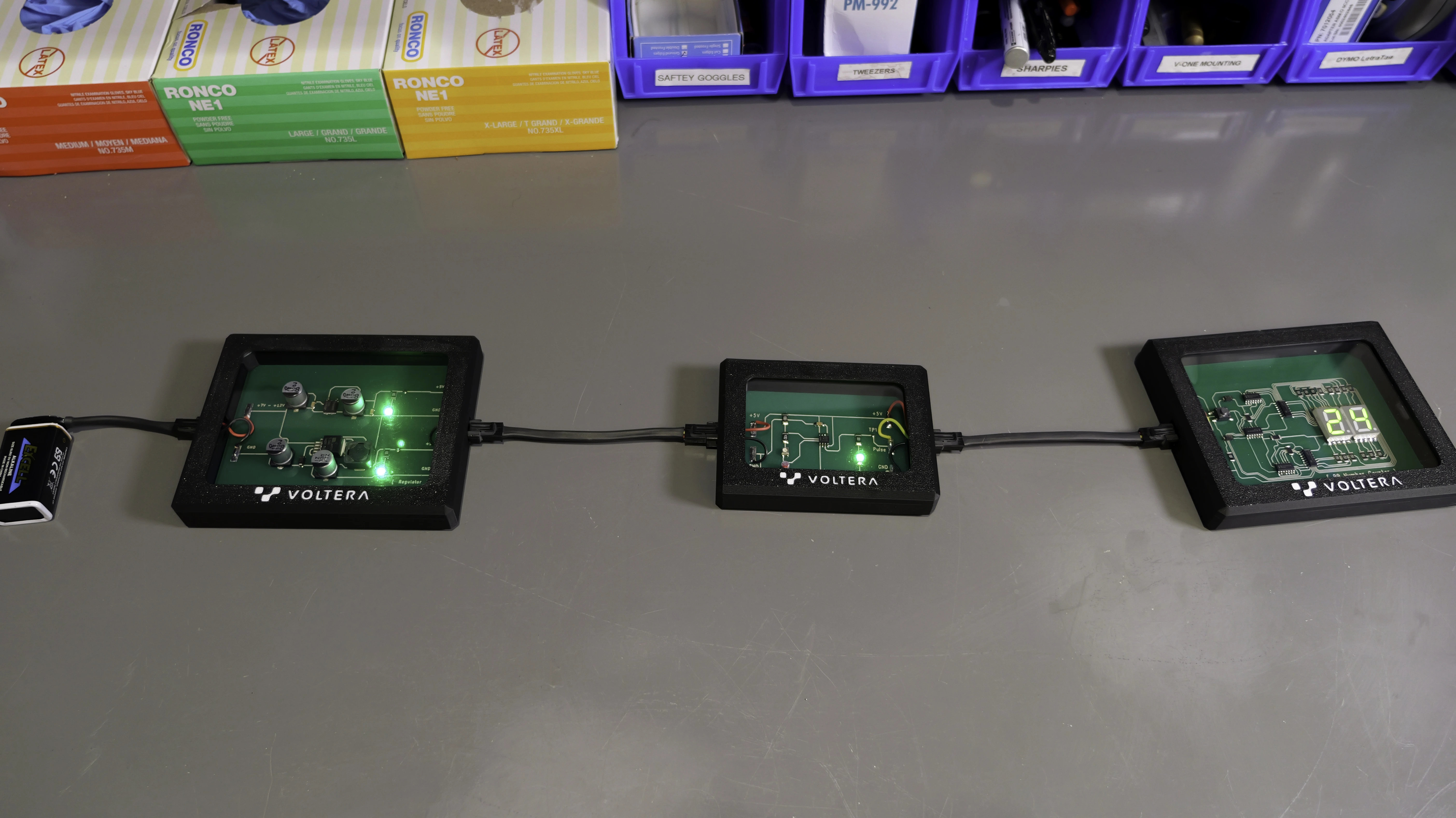
When connected to a 7V–12V DC source, the system should function as follows:
- The voltage regulator board converts the input to a steady 5V output.
- The pulse generator board uses this 5V supply to create adjustable pulse signals.
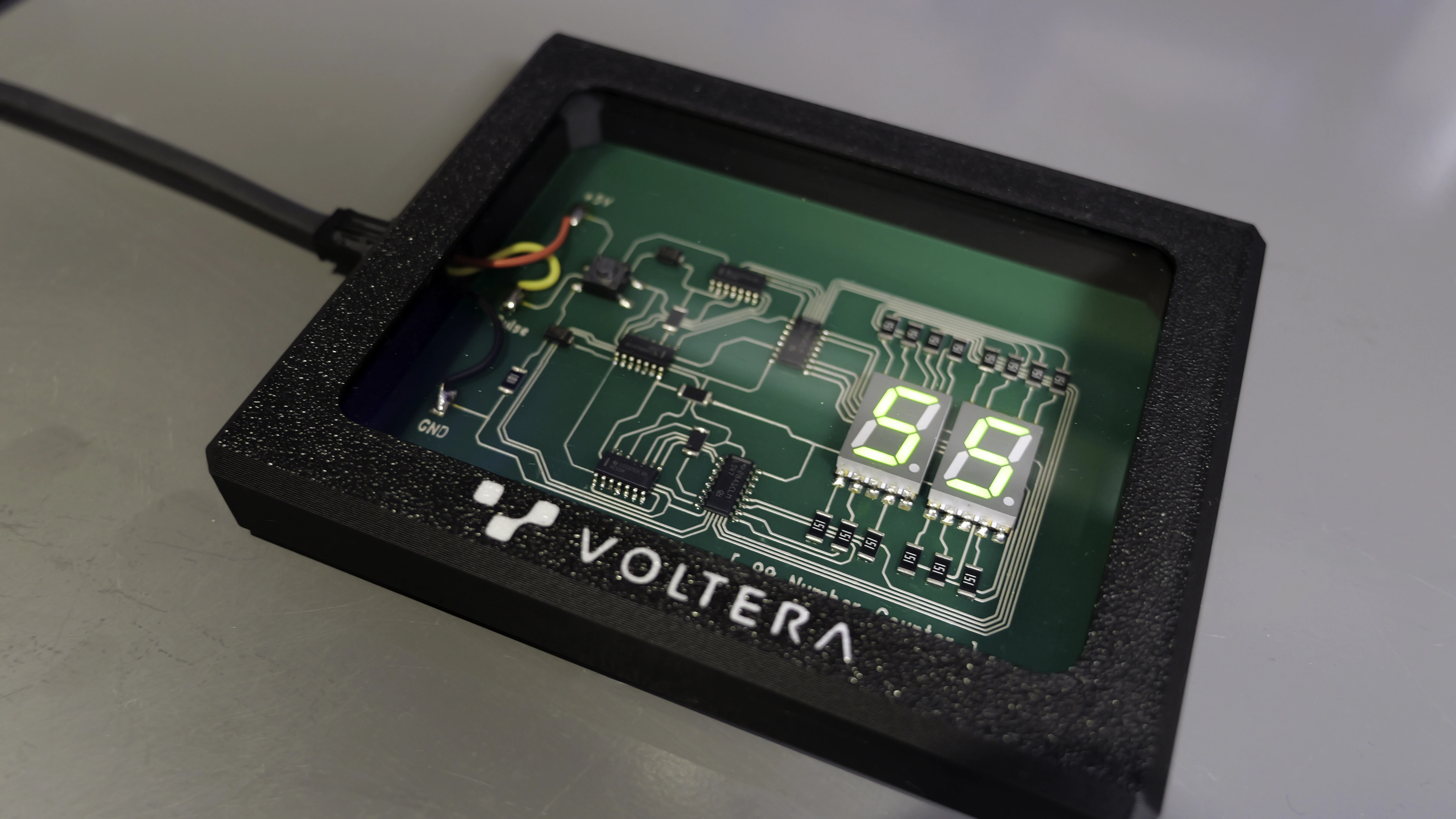
- The decimal counter board drives two seven-segment displays to count from 00 to 99 at a speed controlled by the pulse generator.
Functionality
When powered by a 9V battery, the circuit successfully counted from 0 to 99 at an adjustable speed. A reset button allowed restarting the sequence, and the integration of both a linear regulator (78M05) and switching regulator (LM2575) on the same board provided a practical way to compare their efficiency, thermal behavior, and noise generation.
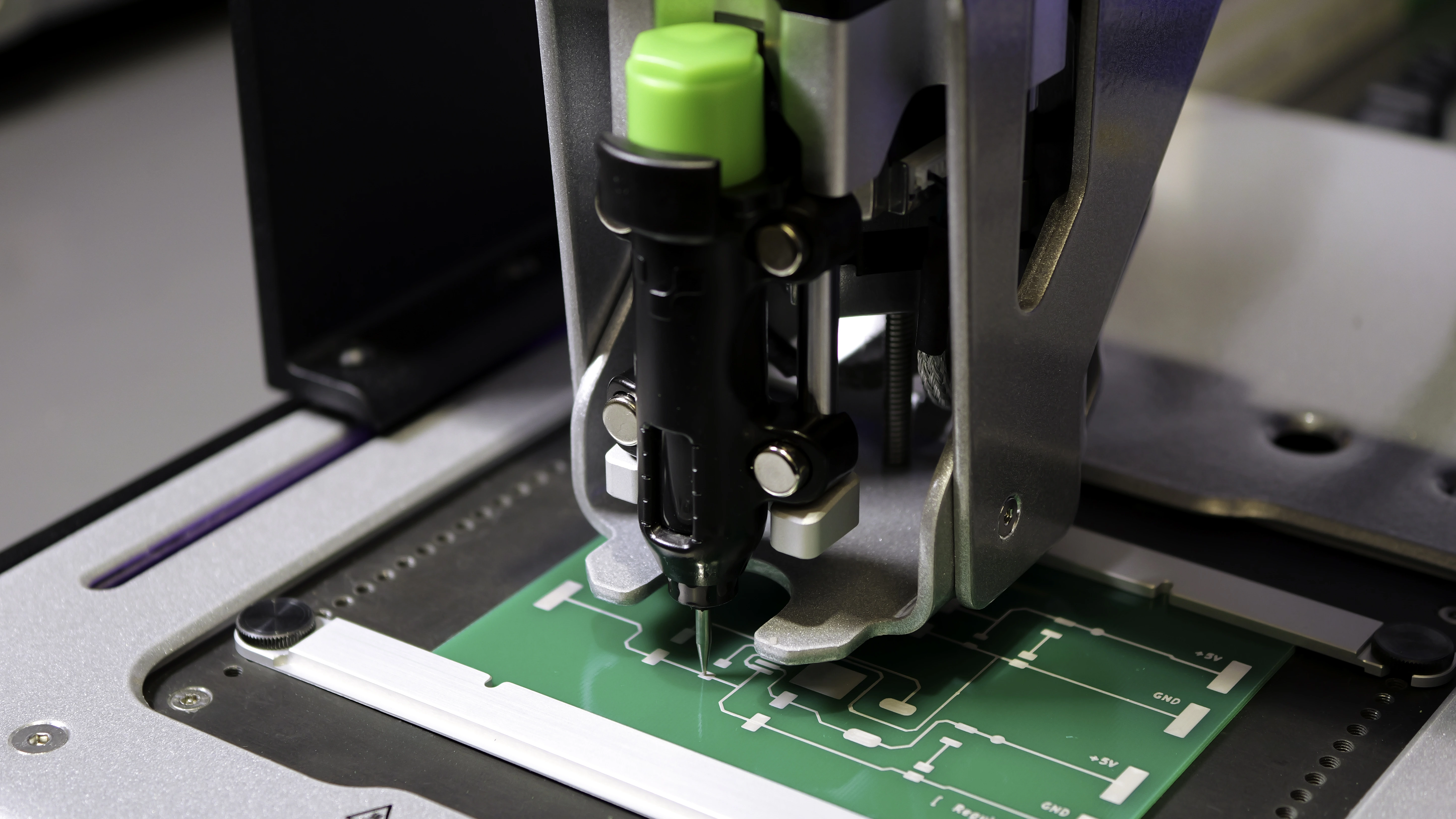
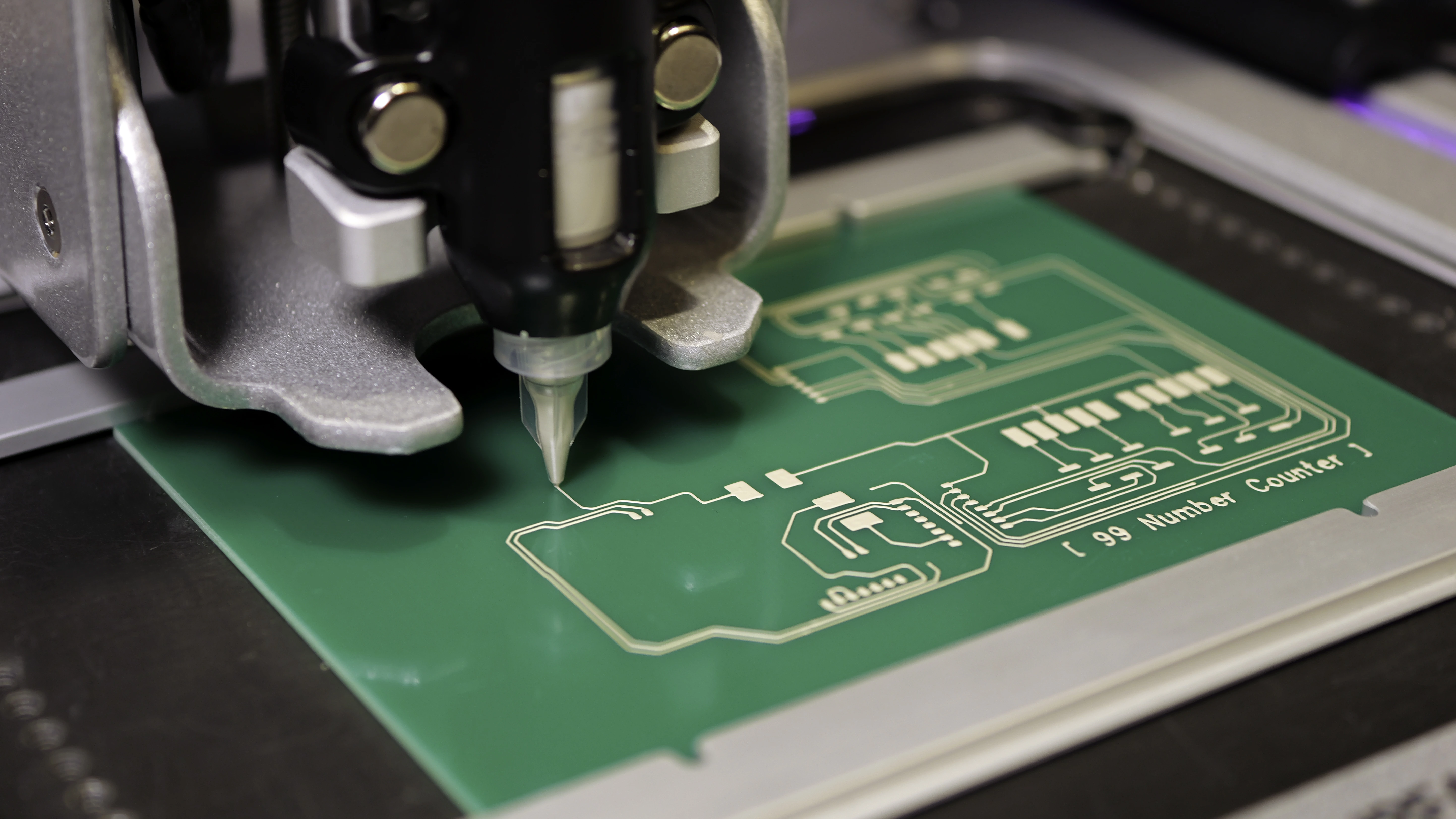
Printing the boards on V-One
Voltage regulator board
This board converts a 9V input into a steady 5V output. It includes the following components:
| Part | Part name | Specification | Quantity |
|---|---|---|---|
| U1 | SMD regulator | 78M05 (linear) | 1 |
| U2 | SMD regulator | LM2575 (switching) | 1 |
| D1, D3 | SMD LED | 3528 (3.5 mm × 2.8 mm), green | 2 |
| R1, R2 | SMD resistor | 5025 (5 mm × 2.5 mm), 330 Ω | 2 |
| C2 | SMD capacitor | 3216 (3.2 mm × 1.6 mm), 0.1 µF | 2 |
| C1, C3, C5 | SMD electrolytic capacitor | 10 mm × 10 mm, 100 µF | 3 |
| C6 | SMD electrolytic capacitor | 8 mm × 10 mm, 330 µF | 1 |
| D2 | SMD diode | DO214AC | 1 |
| L1 | SMD inductor | 330 µH (12.5 mm × 12.5 mm) | 1 |
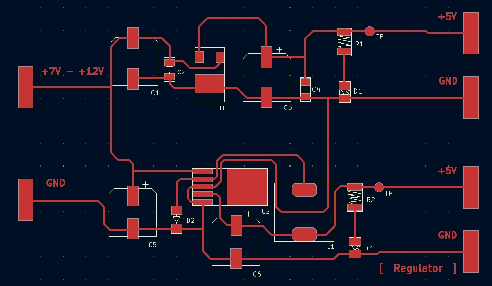
Voltage regulators maintain a stable output voltage regardless of fluctuations in input voltage or load conditions. They play a critical role in circuit stability by preventing voltage spikes or drops that could damage components. In this circuit, we included two different types of regulators for ease of comparison.
The 78M05 linear regulator (U1) dissipates excess energy as heat, providing a stable 5V output at lower efficiency. In contrast, the LM2575 switching regulator (U2) achieves higher efficiency by rapidly switching an internal transistor to store energy in an inductor (L1) and capacitor (C6), though this can introduce noise into the circuit due to rapid switching.
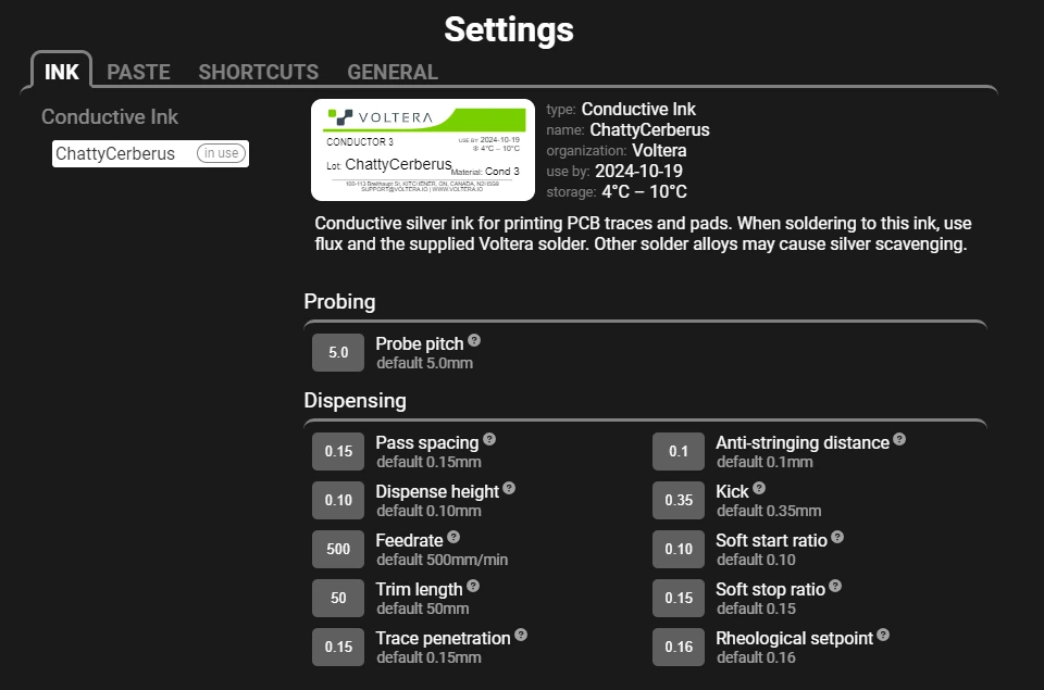
| Ink | Voltera Conductor 3 silver ink |
| Substrate | 3” × 4” FR1 board |
| Nozzle type | Voltera disposable nozzle |
| Probe pitch | 5 mm |
| Probe time | 7 minutes 58 seconds |
| Print time | 10 minutes 52 seconds |
| Cure Time and Temperature | 90°C for 5 minutes, and then 170°C for 15 minutes |
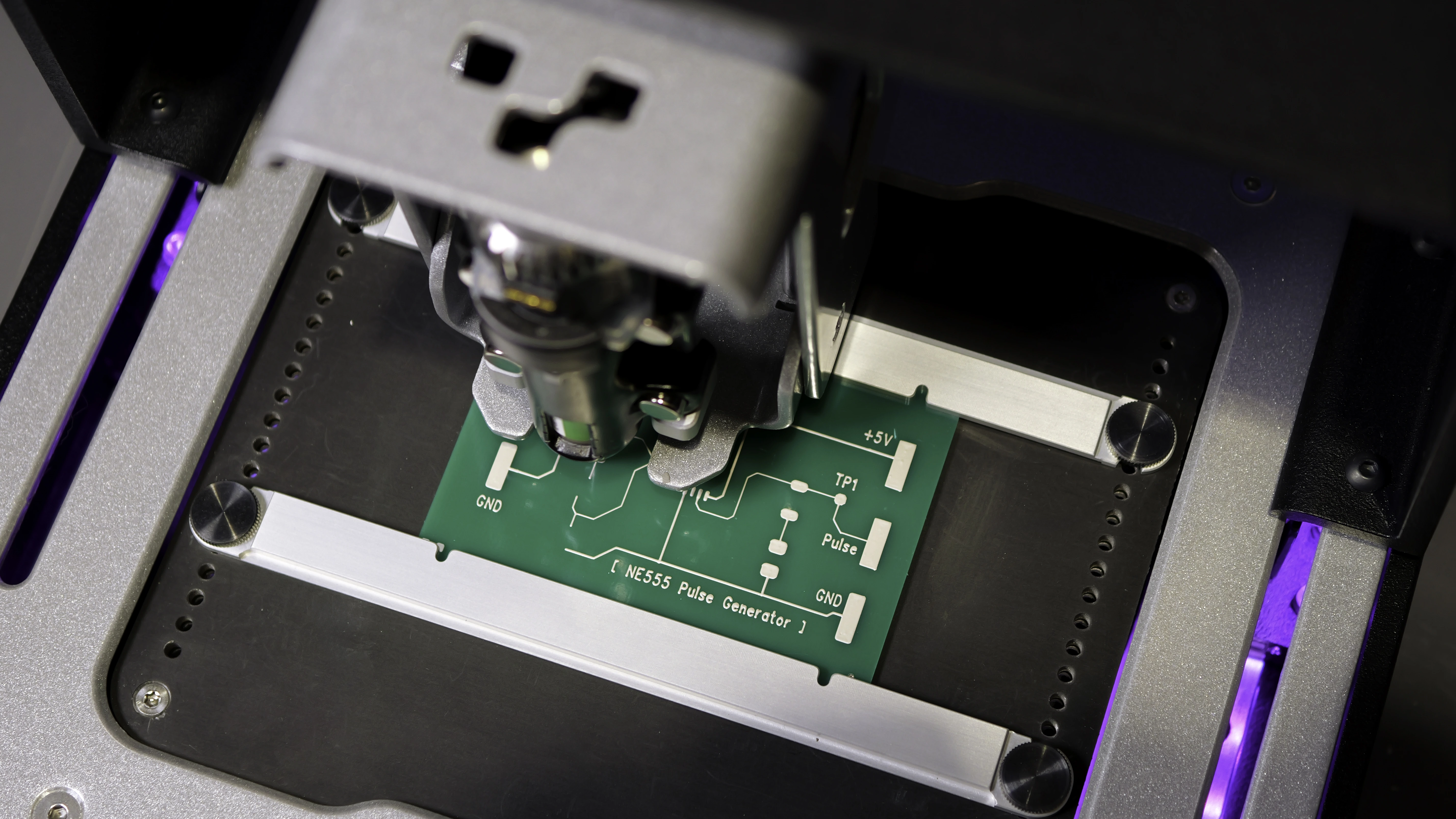
Pulse generator board
This board uses a 555 timer IC (NE555) to generate adjustable pulse signals that drive the decimal counter board. It includes the following components:
| Part | Part name | Specification | Quantity |
|---|---|---|---|
| U1 | IC | NE555 (SOIC package) | 1 |
| D1 | LED | 3528 (3.5 mm × 2.8 mm), green | 1 |
| R1 | SMD resistor | 5025 (5 mm × 2.5 mm), 100 KΩ | 1 |
| R2 | SMD resistor | 5025 (5 mm × 2.5 mm), 47 KΩ | 1 |
| R4 | SMD resistor | 5025 (5 mm × 2.5 mm), 330 Ω | 1 |
| C2 | SMD capacitor | 3216 (3.2 mm × 1.6 mm), 0.1 µF | 1 |
| C1 | SMD electrolytic capacitor | 4 mm × 5 mm, 1 µF | 1 |
| R3 | Variable resistor | SMD PVG3 1 MΩ | 1 |
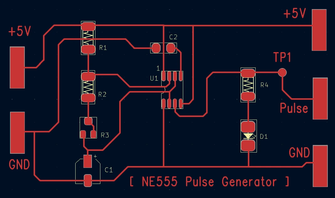
The NE555 timer (U1) is a versatile and widely-used integrated circuit (IC) that can generate stable time delays or oscillations, depending on the external components configured around it. On this board, it operates in astable mode to generate continuous pulse signals.
The variable resistor (R3) functions as a potentiometer in this circuit, altering the charging and discharging time of capacitor C1. This adjusts the pulse frequency, which controls the counting speed of the seven-segment displays on the decimal counter board.
The green LED (D1) blinks in sync with the output pulses.
| Ink | Voltera Conductor 3 silver ink |
| Substrate | 3” × 4” FR1 board |
| Nozzle type | Voltera disposable nozzle |
| Probe pitch | 5 mm |
| Probe time | 5 minutes 12 seconds |
| Print time | 7 minutes 5 seconds |
| Cure Time and Temperature | 90°C for 5 minutes, and then 170°C for 15 minutes |
Decimal counter board
This board drives two seven-segment displays to count from 00 to 99, with adjustable speed (by the pulse generator board) and a reset function. It includes the following components:
| Part | Part name | Specification | Quantity |
|---|---|---|---|
| U5 | IC | SMD 74LS08 (AND gate) | 1 |
| U3, U4 | IC | SMD 74LS47 (BCD-to-7-segment decoder) | 2 |
| U1,U2 | IC | SMD 74LS93 (4-bit binary counter) | 2 |
| SW1 | Push switch | SMD 7 mm × 7 mm | 1 |
| D1, D2 | SMD diode | DO214AC | 2 |
| R15 | SMD resistor | 5025 (5 mm × 2.5 mm), 100 Ω | 1 |
| R1-14 | SMD resistor | 5025 (5 mm × 2.5 mm), 150 Ω | 14 |
| FND1, FND2 | 7-segment display | WL-S7DS (common anode) | 2 |
| JUMPER | SMD jumper | 5025 (5 mm × 2.5 mm), 0 Ω resistor | 3 |
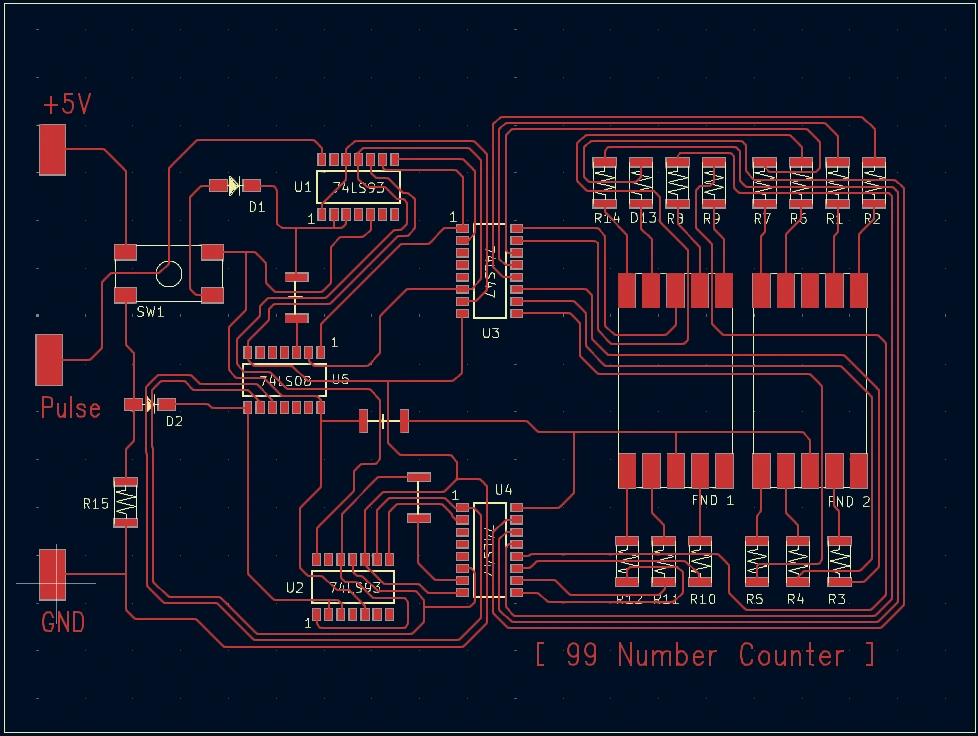
A seven-segment display consists of seven individual LEDs arranged to form the shape of the number 8. By turning specific segments on or off, the display can represent any numeral between 0 and 9.
In this circuit, the 74LS93 counters (U1, U2) process incoming pulses into binary-coded decimal (BCD) outputs. The 74LS47 decoders (U3, U4) convert BCD signals into segment activation patterns for the seven-segment displays (FND1, FND2). A manual reset button (SW1) allows restarting the count.
| Ink | Voltera Conductor 3 silver ink |
| Substrate | 3” × 4” FR1 board |
| Nozzle type | Voltera disposable nozzle |
| Probe pitch | 5 mm |
| Probe time | 9 minutes 43 seconds |
| Print time | 12 minutes 19 seconds |
| Cure Time and Temperature | 90°C for 5 minutes, and then 170°C for 15 minutes |
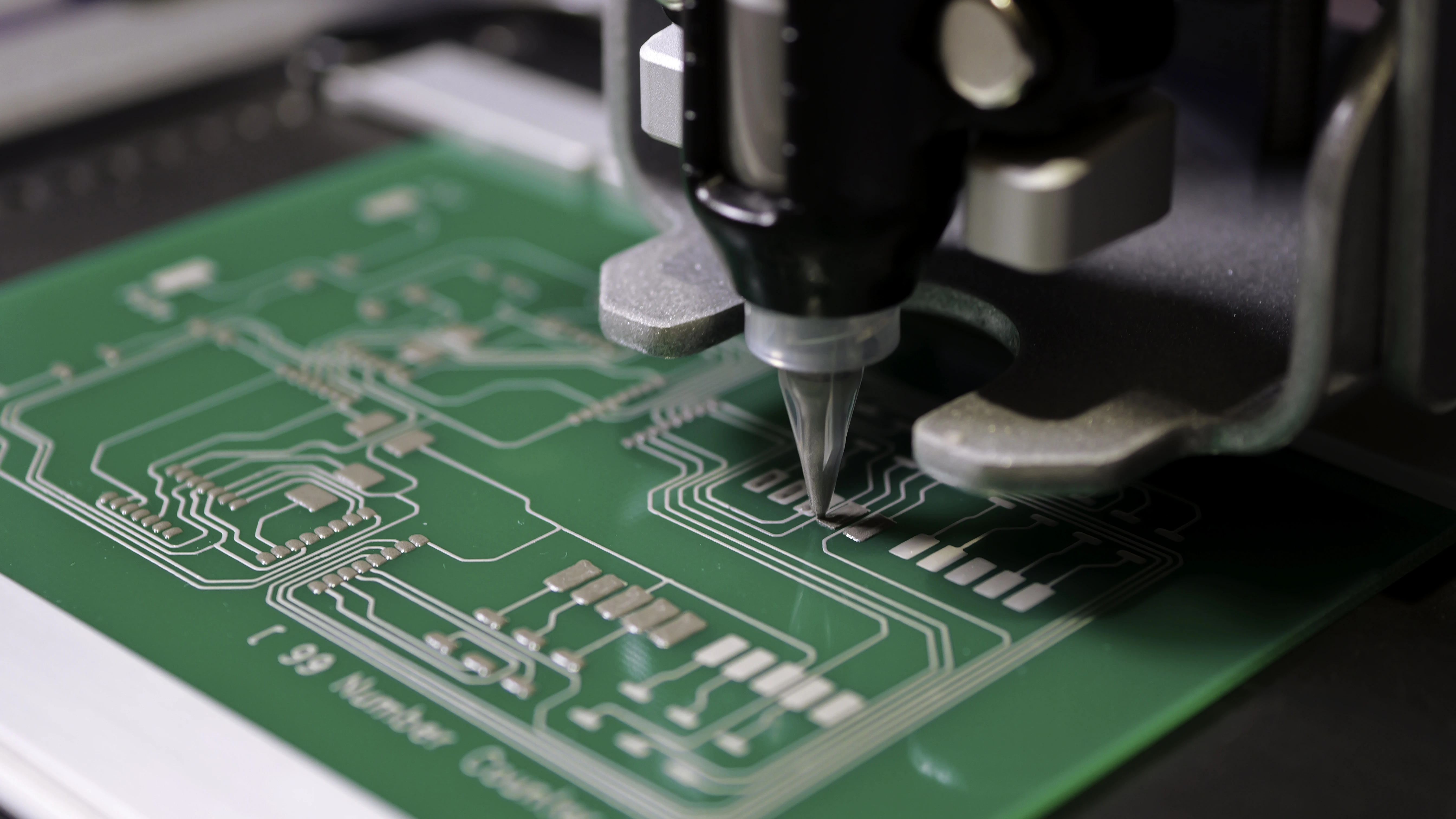
Post-processing
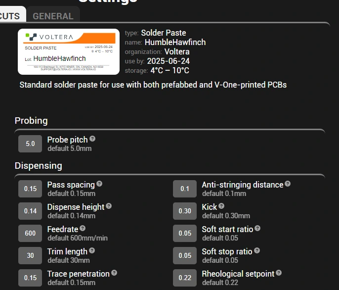
Populating and reflow
After all three circuits were cured, we dispensed solder paste using V-One and carefully populated the components using a pair of tweezers. The solder paste was then reflowed on V-One’s heated bed.
| Parameters | Voltage regulator board | Pulse generator board | Decimal counter board |
|---|---|---|---|
| Paste | Voltera T4 solder paste | Voltera T4 solder paste | Voltera T4 solder paste |
| Substrate | 3” × 4” FR1 board | 3” × 4” FR1 board | 3” × 4” FR1 board |
| Nozzle type | Voltera disposable nozzle | Voltera disposable nozzle | Voltera disposable nozzle |
| Probe time | 2 minutes 13 seconds | 1 minute 19 seconds | 2 minutes 41 seconds |
| Print time | 7 minutes 45 seconds | 4 minutes 4 seconds | 7 minutes 14 seconds |
| Reflow time and temperature | 140°C for 45 seconds, and then 190°C for 30 seconds | 140°C for 45 seconds, and then 190°C for 30 seconds | 140°C for 45 seconds, and then 190°C for 30 seconds |
Connecting the boards
The three boards were linked using JST-SM connectors and wires. We connected the voltage regulator board to a battery and the pulse generator. We then connected the pulse generator outputs to the decimal counter’s clock input pins.
Printing enclosures
To protect the circuits from any impact during handling, we designed and 3D printed three enclosures using PLA filament.
Challenges and advice
Troubleshooting interconnected circuits
Errors in interconnected systems could originate from any board, which made troubleshooting a bit more complex than a single board. To streamline the process, we recommend checking component polarity and orientation before populating the components, and reference their datasheets when necessary. Additionally, it’s helpful to check for continuity with a multimeter, or with an oscilloscope to calculate and view the frequency of the pulses.
Conclusion
This project highlights the potential of additive PCB prototyping in electronics education. By combining theory and practice, students can explore how digital counting systems function, understand the role of BCD-to-seven-segment conversion, and observe how timing signals interact with display components. Direct ink writing platforms like V-One empower the next generation of engineers to innovate beyond breadboards and rapidly iterate on electronics designs.
If you are interested in exploring other PCB prototyping projects we have completed, take a look at:
- Printing a Control Board for a Line Following Robot with Silver Ink on FR1
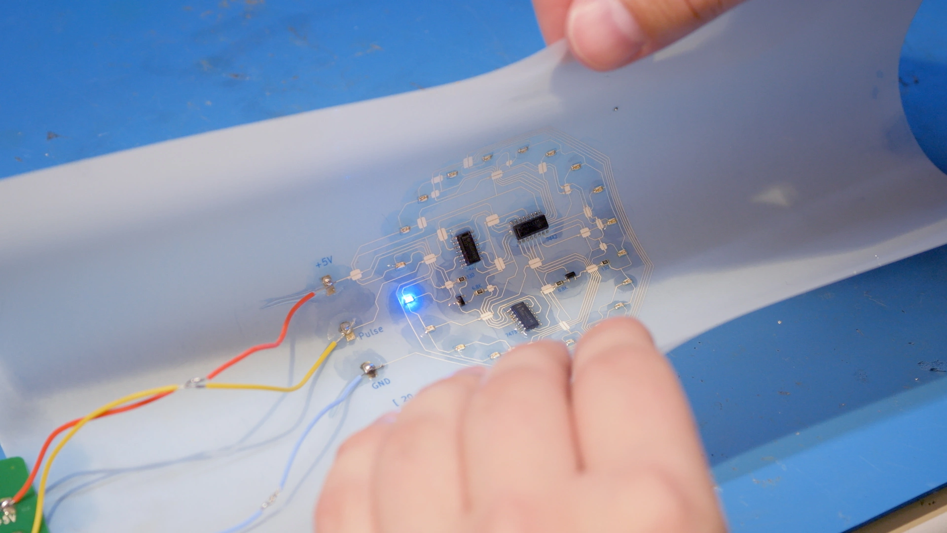
- Printing a Flexible PCB with Silver Ink on PET
- Dispensing Solder Paste on Factory Fabricated PCBs
Want to be notified when we post new white papers? Sign up for our newsletter.
Printing multilayer flexible, stretchable, and conformable electronics?
NOVA’s Plan feature makes it easy.