White paper
Developing a Custom Carbon Ink for Printing a Variable Resistor on PET
Custom resistive inks are formulated with carbon, metal, or hybrid particles, along with binders and solvents, to support applications in dimmers, sensors, and potentiometers. Their resistivity can be adjusted through particle concentration or trace geometry while balancing viscosity and adhesion.

- Polyethylene terephthalate (PET)
- 2" × 3" FR1 board
- NOVA materials dispensing system
- V-One PCB printer
- 150 µm Subrex nozzle
- Nordson EFD 7018333 dispensing tip
- Voltera disposable nozzle
- Dual asymmetric centrifugal mixer
- Magnetic stirrer
- Bambu X1 Carbon 3D printer
Project overview
Purpose
In this project, we demonstrate the development of a carbon resistive ink through testing different ink formulations and validating the performance through a potentiometer and an LED circuit.
Design
We divided the design into four parts:
- Developing the carbon resistive ink
- Printing the potentiometer circuit
- Printing the LED circuit
- 3D printing the enclosure with a sliding wiper
Desired outcome
The goal was to develop an ink with great printability, which, for this project, we measured by viscosity (between 1,000–10,000 cPs, compatible with direct ink writing and screen printing). We also aimed to achieve excellent adhesion to the substrate, with no flaking or cracking after curing at 90°C for 5 minutes. In addition, the ink should support a potentiometer to function properly, which means the resistance range should fall between 600 Ω to 6000 Ω.
Functionality
When connected to the LED dimmer board (powered by a 9V battery), sliding the wiper altered the potentiometer’s resistance, dimming or brightening three LEDs. Resistivity was tunable by adjusting carbon concentration, curing time and temperature, or printing thicker or shorter traces.
While this formulation served as a functional prototype, higher carbon loadings (up to 20%) could be explored for enhanced conductivity, though viscosity adjustments would be necessary to maintain printability. Users can also change resistance by modifying the size of the conductive pad.
Developing the carbon resistive ink*
The development of custom functional inks, whether conductive, dielectric, resistive, or semiconducting, requires balancing particle loading, solvent compatibility, and binder selection to achieve target electrical and mechanical properties. While conductive inks rely on metallic particles like silver for low resistivity, resistive inks prioritize tunable compositions.
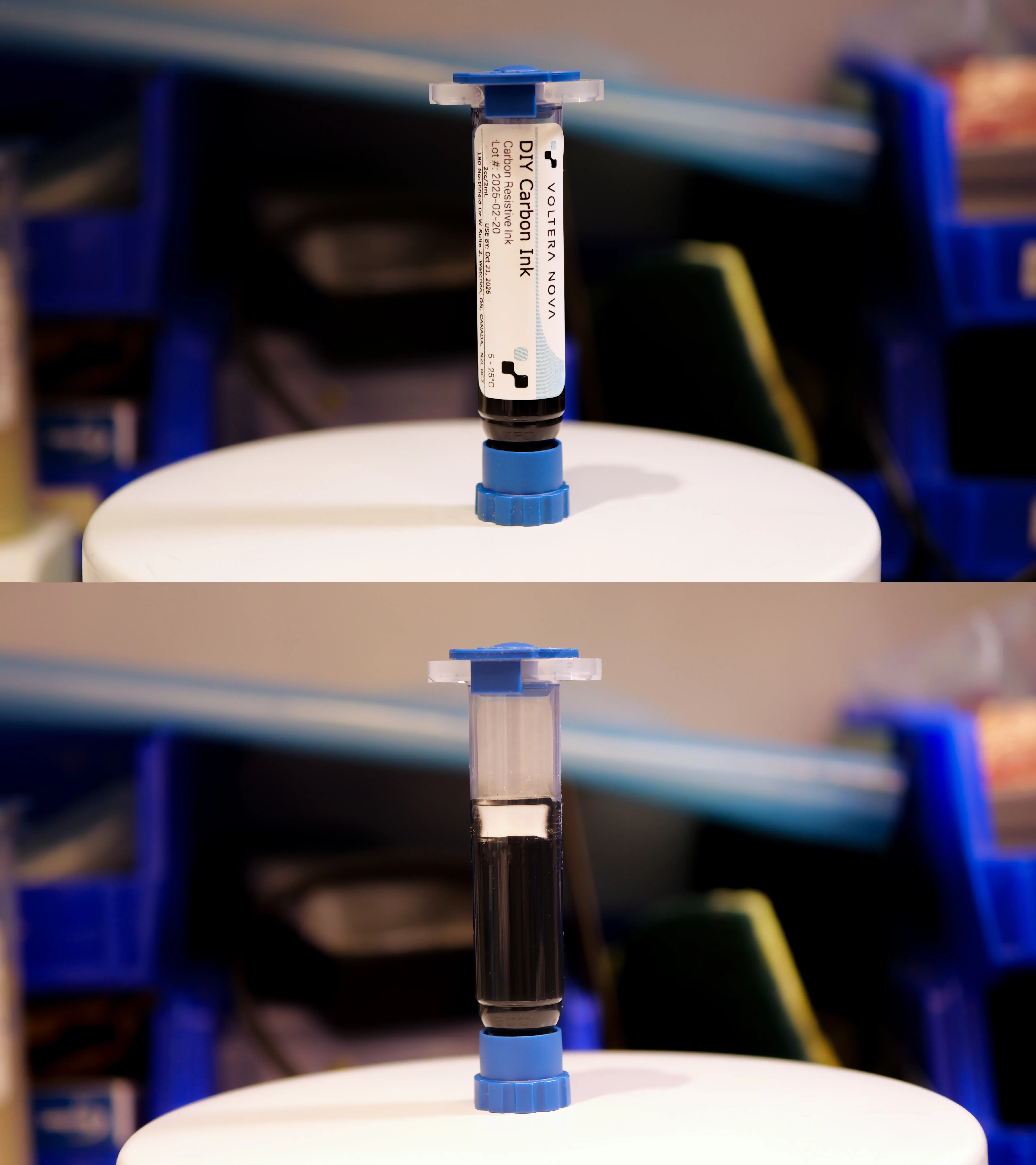
Guided by these principles, we formulated a carbon-based resistive ink using carbon black for its cost-effectiveness and moderate conductivity, paired with PVP as a binder to enhance particle dispersion and substrate adhesion. The solvent blend, 2-(2-butoxyethoxy)ethyl acetate and ethanol, balanced evaporation rates and ink stability, critical for nozzle performance and film uniformity. Our iterative testing refined these ratios for compatibility with NOVA and the intended application.
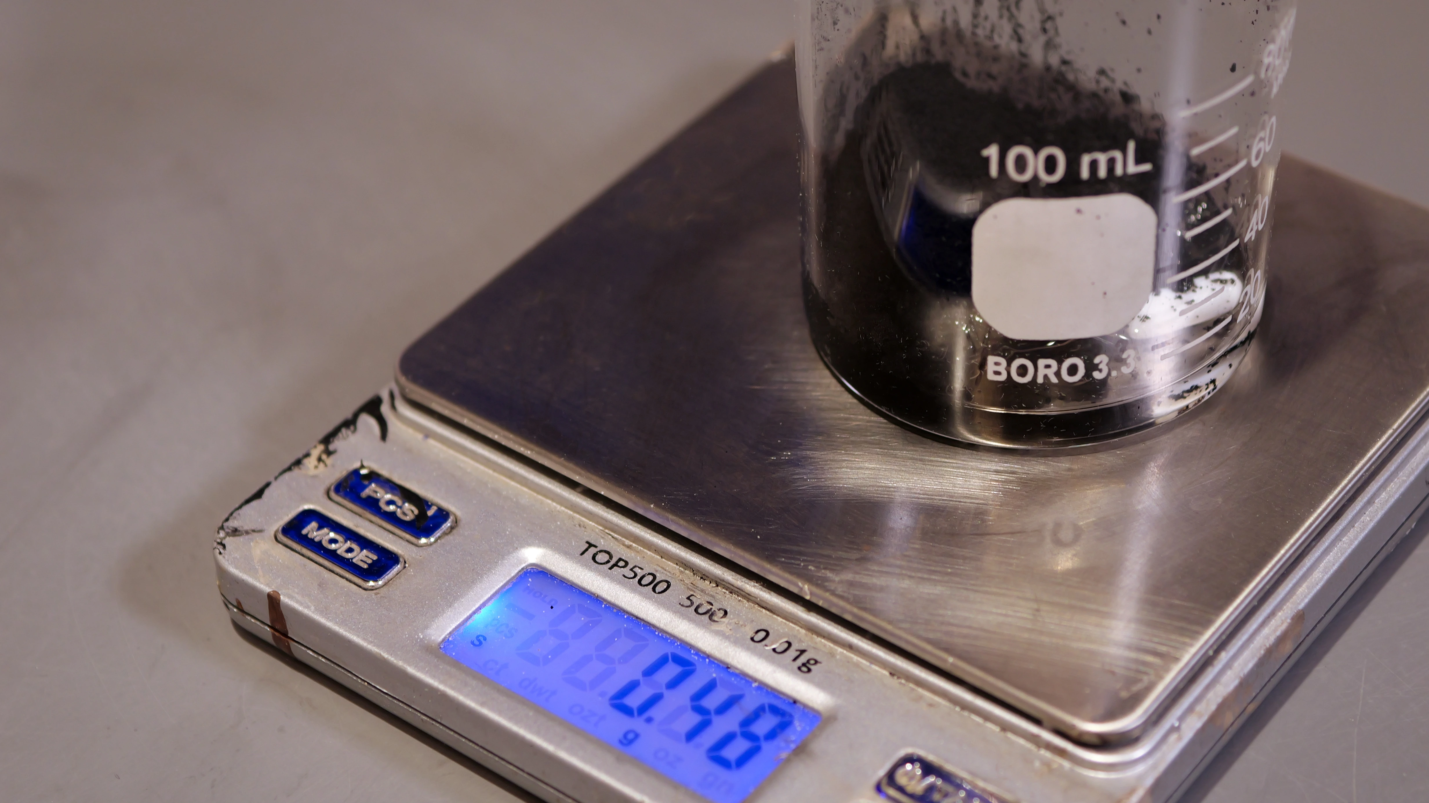
We started by dissolving 1.04 g of PVP into 4.88 g of ethanol using a magnetic stirrer at 1,500 rpm for 15 minutes. We then added 0.48 g of carbon black to the PVP-ethanol solution to minimize airborne particles, followed by the dropwise incorporation of 1.6 g of 2-(2-butoxyethoxy)ethyl acetate. We stirred the mixture for an additional 15 minutes under parafilm to prevent solvent evaporation, which resulted in a stable, homogenous ink.
The final composition included 13% PVP as a binder, 6% carbon black for conductivity, 20% 2-(2-butoxyethoxy)ethyl acetate as a solvent, and 61% ethanol to stabilize the dispersion. This combination achieved a viscosity of about 1,500 cps, enabling smooth dispensing through the Nordson EFD 7018333 dispensing tip with an inner diameter of 250 µm.
| Component | Weight % | 8 g batch (g) |
|---|---|---|
| PVP | 13 | 1.04 |
| Carbon Black | 6 | 0.48 |
| 2-(2-Butoxyethoxy)ethyl acetate | 20 | 1.6 |
| Ethanol | 61 | 4.88 |
Final ink formulation**
* Follow the guidelines in the safety data sheet when handling the carbon black powder.
** The formulation in the table is for an 8 g resistive ink and is scalable using the provided weight percentages.
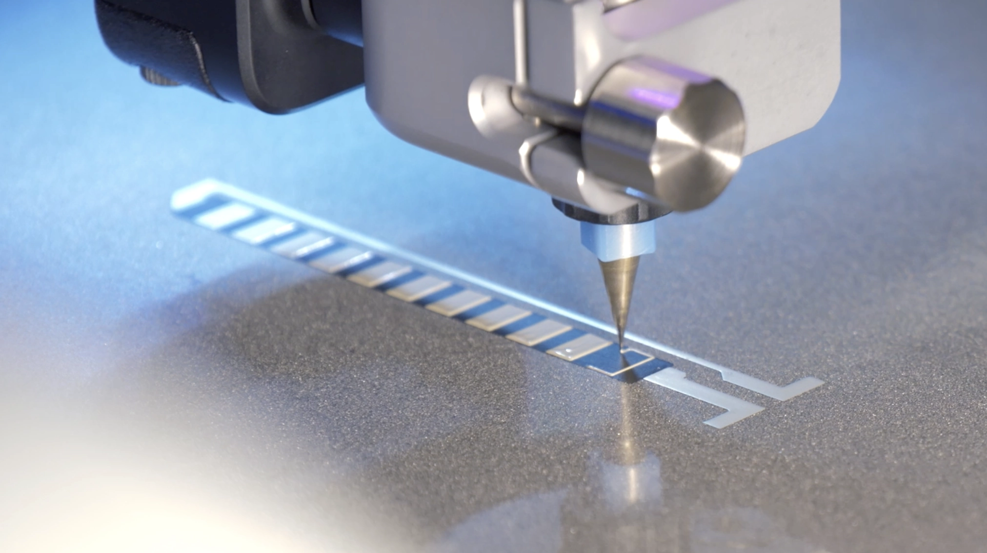
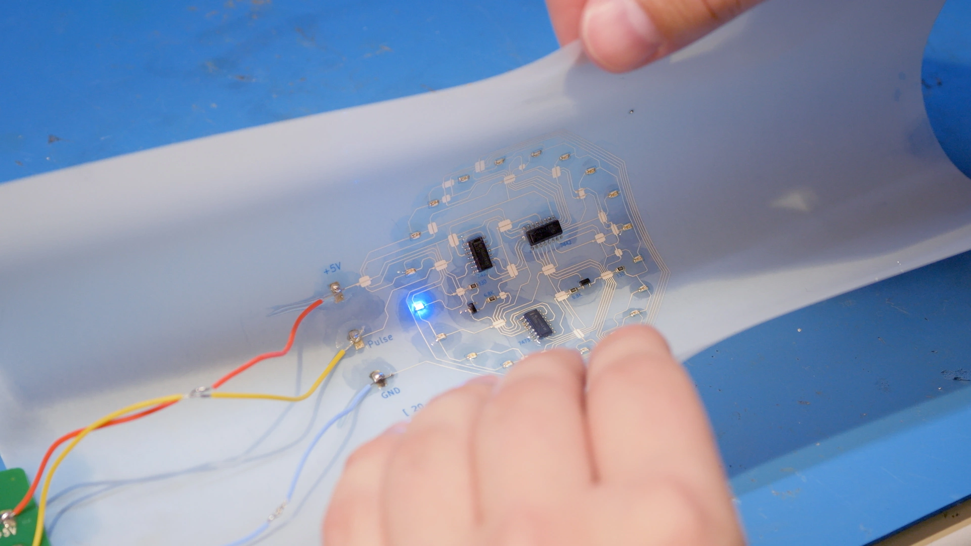
Printing the potentiometer circuit
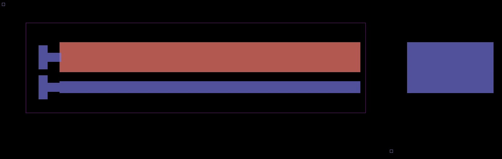
This circuit consists of two layers:
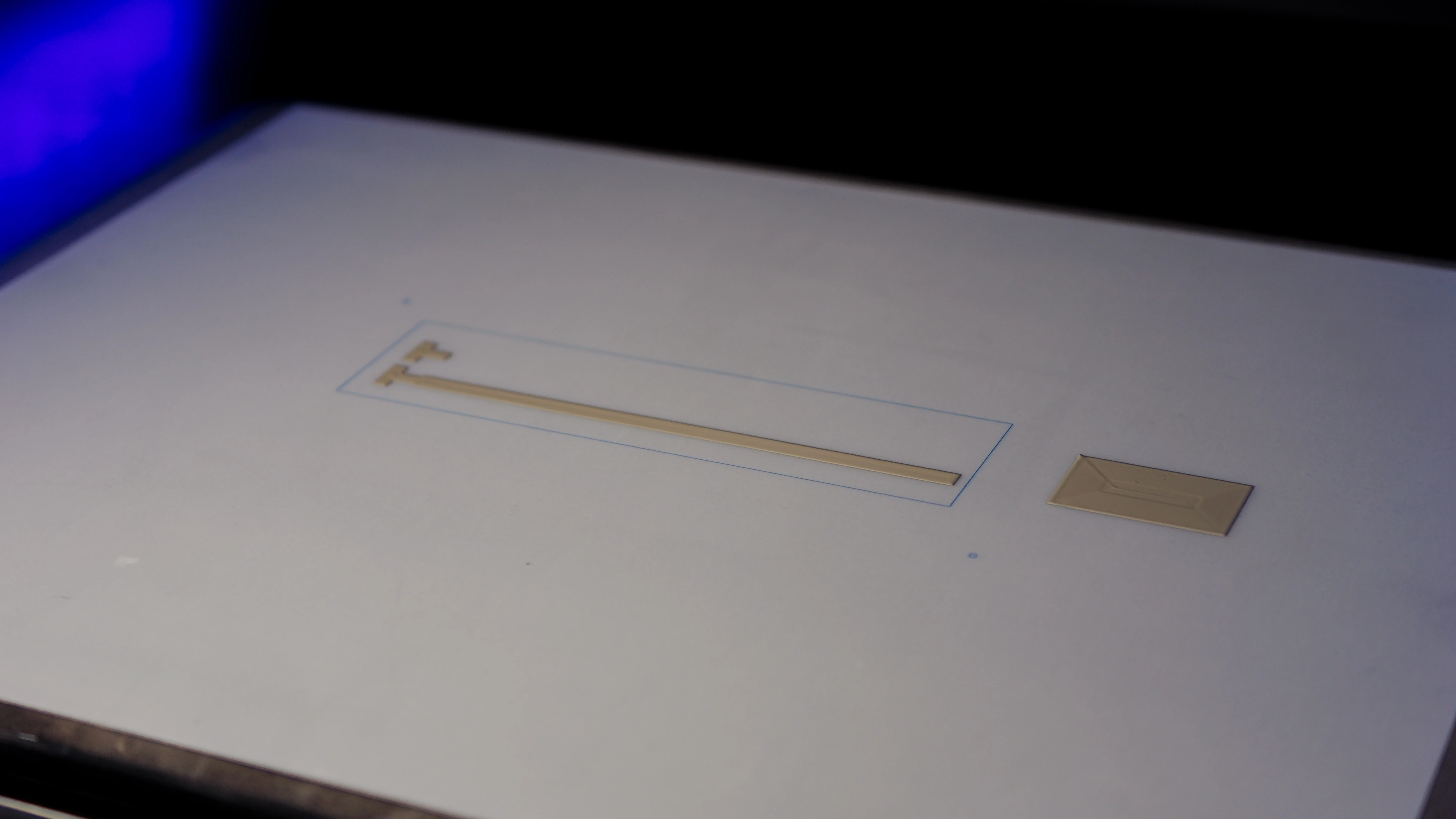
- Bottom conductive layer (in blue): Includes silver traces for solderable contacts, as well as a
conductive pad to be glued onto the wiper of the potentiometer. Sliding the wiper up and down alters the carbon resistor’s effective length and changes the resistance of the circuit.
- Top resistive layer (in red): Carbon traces for the resistive element
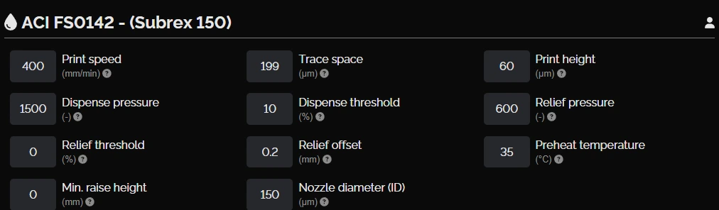
| Ink | ACI FS0142 flexible silver ink |
| Substrate | PET |
| Nozzle type | Subrex nozzle, 150 µm inner diameter |
| Probe pitch | 5 mm |
| Probe time | 2 minutes 38 seconds |
| Print time | 12 minutes 24 seconds |
| Cure Time and Temperature | 150°C for 15 minutes |
Bottom conductive layer
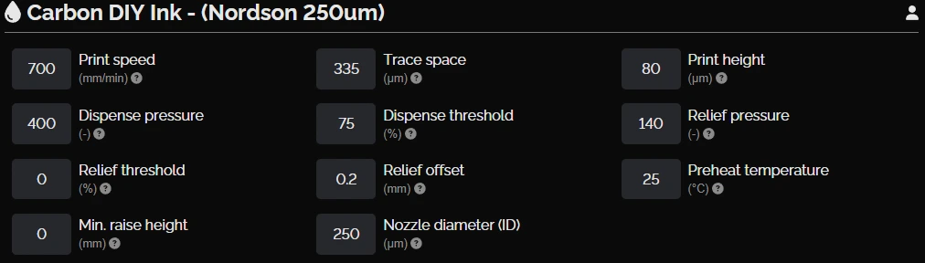
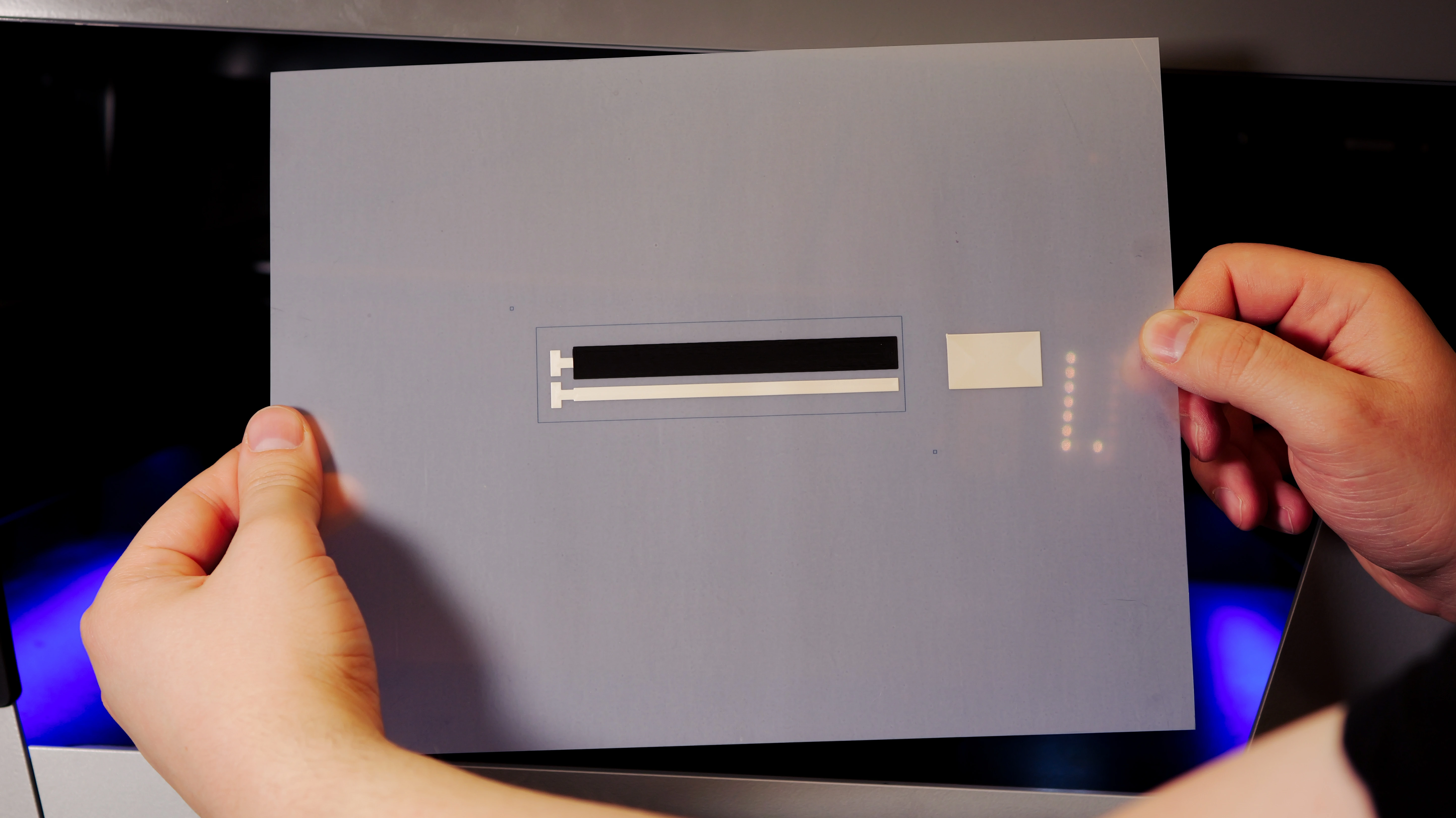
Top resistive layer
| Ink | Carbon resistive ink developed by Voltera’s Applications team |
| Substrate | PET |
| Nozzle type | Nordson EFD 7018333 dispensing tip, 250 µm inner diameter |
| Probe pitch | 5 mm |
| Probe time | 2 minutes 26 seconds |
| Print time | 4 minutes 25 seconds |
| Cure Time and Temperature | 90°C for 5 minutes |
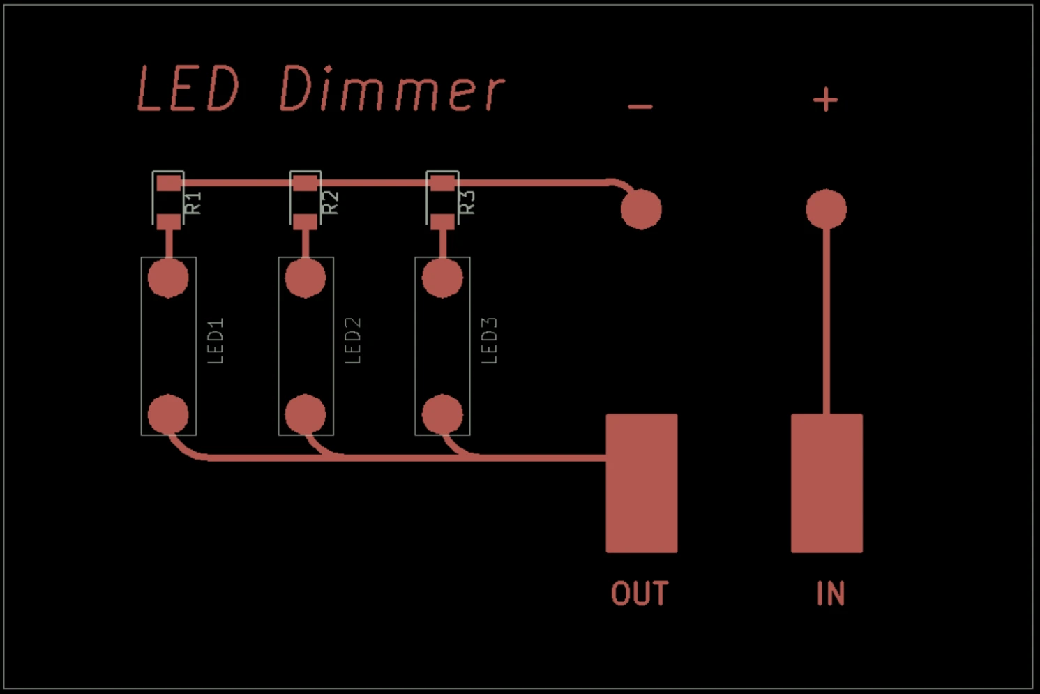
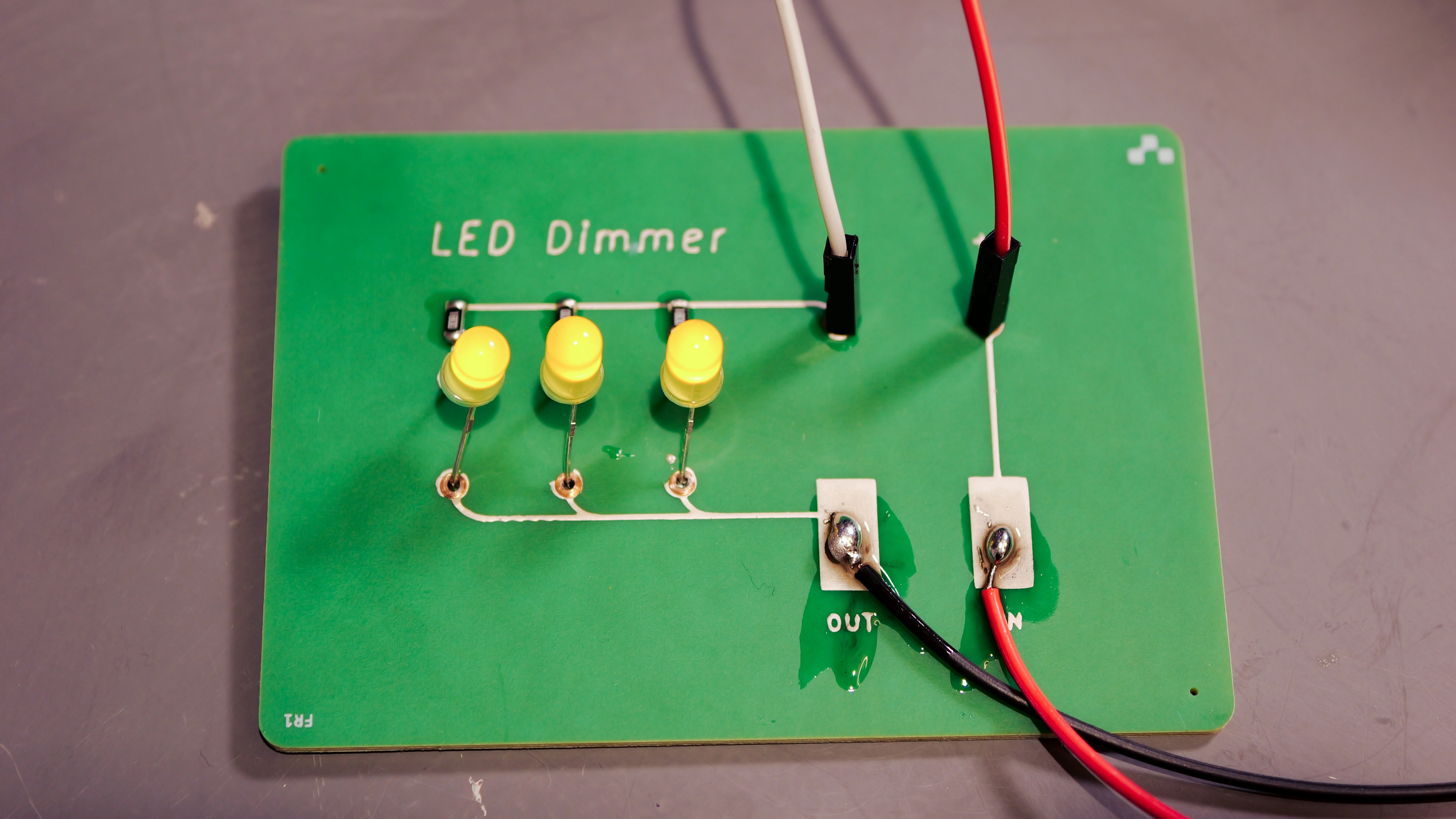
Printing the LED dimmer circuit
This circuit was designed to visually demonstrate resistance changes by linking three LEDs to the potentiometer. Silver traces printed on an FR1 substrate formed conductive pathways, connecting the 9V power input to the potentiometer and LEDs.
| Ink | Voltera Conductor 3 silver ink |
| Substrate | FR1 |
| Nozzle type | Voltera disposable nozzle, 225 µm inner diameter |
| Probe pitch | 5 mm |
| Probe time | About 5 minutes |
| Print time | About 5 minutes |
| Cure Time and Temperature | 90°C for 5 minutes, and then 170°C for 15 minutes |
Once the circuit was cured, we manually placed and soldered the LEDs and reflowed the solder paste on V-One’s heated bed.
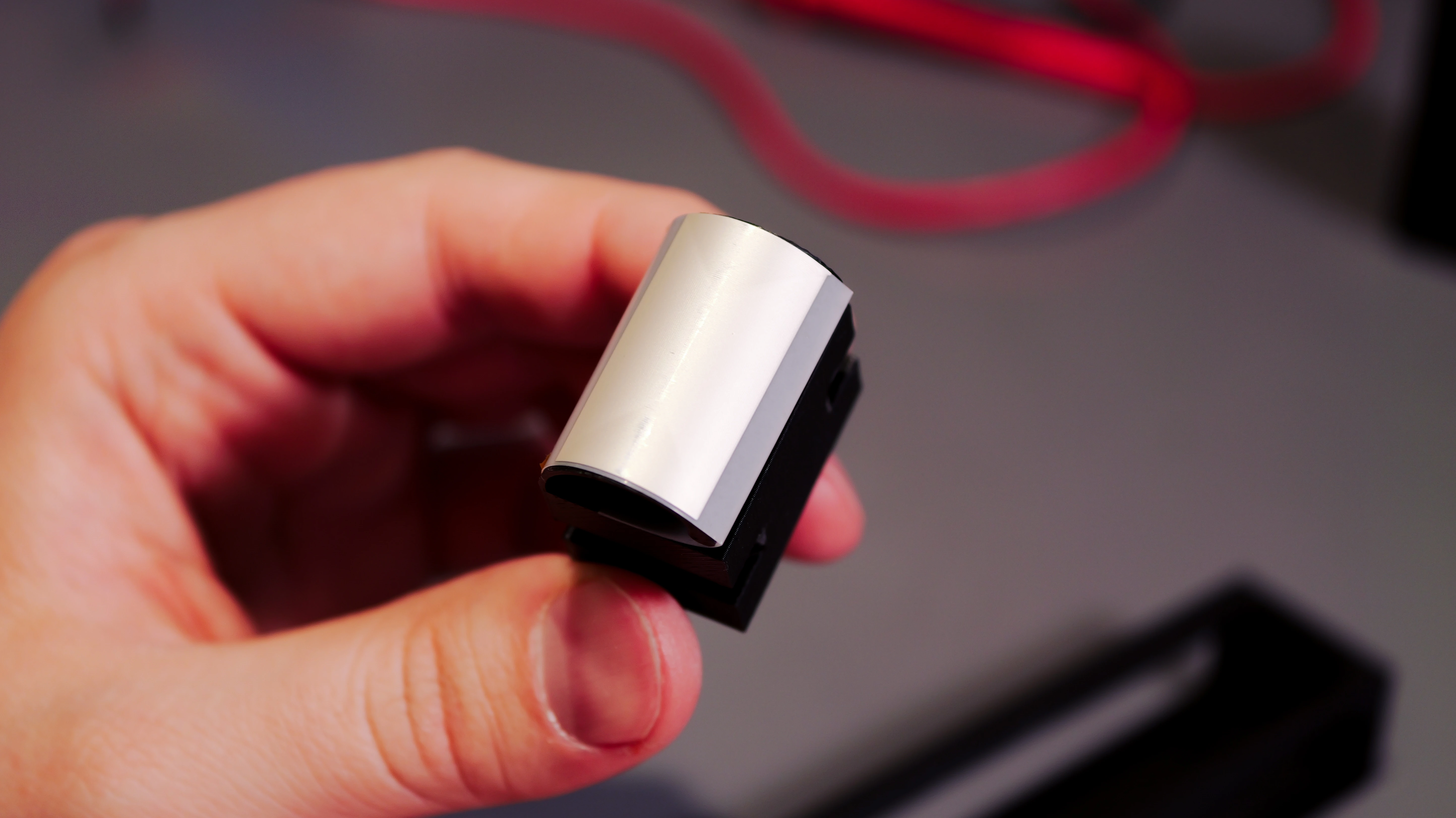
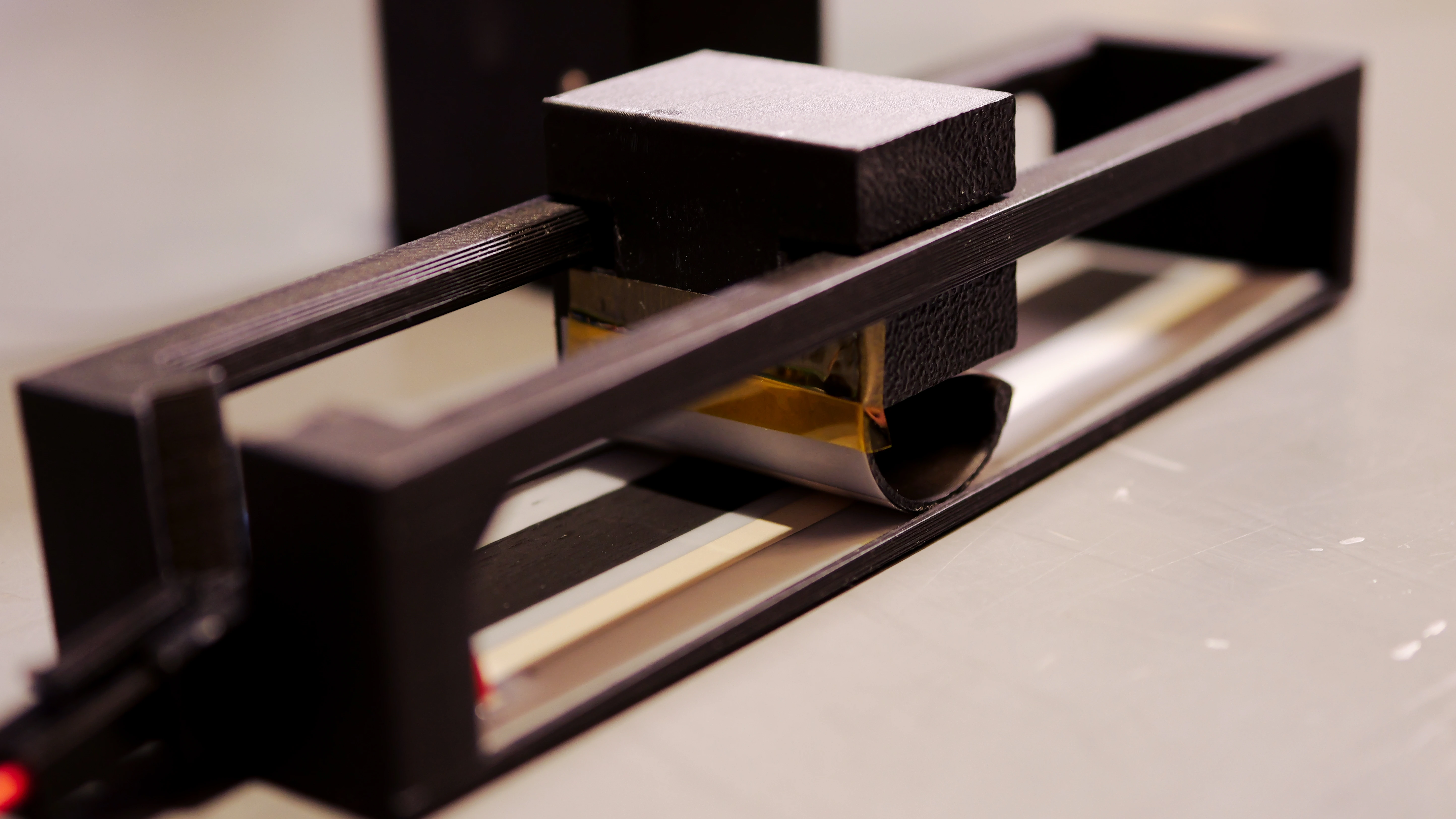
Printing the enclosure
To house the potentiometer, we designed and 3D-printed a custom enclosure using PLA filament. The enclosure features a built-in sliding wiper mechanism for adjusting resistance and a compartment to securely hold the circuit components. After fabricating the enclosure, we cut the potentiometer circuit from the PET sheet and carefully taped it into the enclosure. Next, we soldered wires to the silver pads on the circuit to establish robust electrical connections.
We then taped the conductive pad onto the wiper to ensure reliable contact with the resistive layer. After placing the wiper inside the enclosure, we twisted it 90 degrees to lock it into place. Finally, we connected the potentiometer to the LED dimmer circuit, which enabled real-time resistance adjustments for LED brightness control.
Challenges and advice
Clogging the nozzle
During initial ink formulation trials, the carbon black particles aggregated in the solvent, which caused nozzle clogs and led to incomplete traces. After some investigation, we realized that the issue stemmed from insufficient dispersion stability — carbon particles settled unevenly in the solvent, forming dense clusters that blocked the nozzle.
To address this, we introduced PVP as a dispersant and binder. We also adjusted the solvent ratio, reducing the volatile 2-(2-butoxyethoxy)ethyl acetate and increasing ethanol to improve particle suspension. Additionally, we recommend using a dual asymmetric centrifugal mixer to ensure homogeneous ink mixing. Lastly, we recommend using larger nozzles for particle-laden formulations to reduce shear stress during dispensing, as evidenced by better print results produced by the 330 µm nozzle, compared to the 200 µm nozzle.
Conclusion
As our first custom ink project, the bulk of work involved was iterating on ink formulation, trying to find the balance between printability and functionality. Using NOVA, we validated a new material in less than a month and created a repeatable process for developing carbon resistive ink. NOVA enabled our materials R&D process by allowing us to get immediate feedback on printability, iterate formulations right on our benchtop, and create novel electronics.
If you’re interested in our other projects involving novel inks, take a look at:
- Printing ECG Electrodes with Biocompatible Gold Ink on TPU
- Printing an RFID Tag with Copper Ink on Paper
- Printing Electroluminescent Ink on Paper and PET
Want to be notified when we post new white papers? Sign up for our newsletter.
Printing multilayer flexible, stretchable, and conformable electronics?
NOVA’s Plan feature makes it easy.